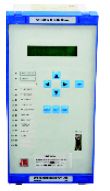
Synchro Check Relay
10 - 49,478 Per Piece
2 Piece(s) (MOQ)
Features Programmable bus voltages Programmable bus frequencies Programmable phase angle difference between two buses Dead bus Active/Inhibit feature History of 5 latest relay closing details Self Supervision facility Application: JNF 060 is used in power systems in order to prevent interconnection of badly synchronized supplies. Synchro check relay is used in series with a breaker closing circuit and automates the operation of synchronizing two buses. Principle of Operation: JNF 060 monitors voltage, frequency and phase angle difference of both the buses. If “dead bus” feature is Inhibit and If the voltage, frequency and the phase angle differences are within the pre-set limits, then the N/O contacts of the relay operates indicating synchronization of the buses else the relay does not operate. If “dead bus” feature is Active and if the status of one of the buses (bus-1) is programmed as “dead bus” and the other (bus-2) is considered normal, Then, the relay operates if the voltage on bus-2 is greater than 80% of the rated voltage and the voltage on bus-1 is lesser than a programmable value (30%-80% of the rated voltage). Output relay can be operated either in continuous mode or pulse mode. In continuous mode, the relay N/O contacts operate after a programmable delay and will remain in that condition until either a synchro check fails or h/w or power on reset occurs. In the pulse mode, the relay N/O contacts operate for a short while and gets released after a fixed delay of 150msec.
...more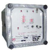
Single Pole Over Current Relay
Application: The relay provides earth fault protection of Generators,Motors, Transformers, Feeder etc., and where definite time protection is required. Principle of Operation: The relay provides single pole over current protection for power systems. Relay operating time is determined by set definite time. The relay measures the current from input CT and if it exceeds the set threshold, it extends a trip signal after the operating time, which is determined by set definite time. The relay output contacts are self reset type. TEST button facilitates testing of relay
...more
Single Pole Definite Time Earth Fault Relay
Application: The relay provides earth fault protection of Generators,Motors, Transformers, Feeder etc., and where definite time protection is required. Principle of Operation: The relay provides earth fault protection for power systems. Relay operating time is determined by set definite time. The relay measures the current from the input CT and if it exceeds the set threshold, it extends a trip signal after the operating time, which is determined by set definite time. The relay output contacts are self reset type. TEST button facilitates testing of relay contacts for trip and alarm circuits.
...more
Self Powered Current Relay
Features No Auxiliary supply Programmable operating characteristics Low burden Wide setting range LED fault flag indication Principle of Operation: If a fault occurs at the distribution end and the respective protective relay operates but the corresponding CB fails to operate then the system may have to face catastrophic consequences. JRC-154 is a instantaneous and definite time over current relay that also monitors the non-potential contacts of the downstream protective relays. The relay is designed to trip the feeder end CB if the protective relay at the distribution end operates but its corresponding CB fails to operate.
...more
Restricted Earth fault Relay
Features Software based design Very sensitive and wide setting range Insensitive to currents at harmonic frequencies Trip test facility Principle of Operation: The Relays JRD 011 & JRD 013 are current operated Microprocessor based, differential relays which work on the high impedance principle. An external series stabilizing resistor is used with this relay to make it a voltage operated relay. The voltage setting of the relay is adjusted to be higher than that developed by the current transformers used for maximum external fault conditions. JRD 011 is a single pole relay where as JRD 013 is a triple pole relay. The sensing current is converted to voltage by an internal resistor and this voltage is fed to a harmonic network which is tuned to fundamental frequency. The output of filter is fed to voltage comparator. When the sensing current signal at the fundamental frequency exceeds the set value,the comparator gates a train of pulses to the processor. The program residing in the CPU performs the function of control and also gives output signals for relay and LED driver circuits. The operation of the relay is indicated by the glowing of a 'Red' LED,which has to be reset manually by means of a 'RESET' push button provided on the front of the relay. A 'Trip Test' push button is also provided in the relay to enable testing of the trip and alarm circuits. When this push button is pressed, the output element of the relay is energized and its contacts close to energize the trip and alarm circuits. The relay will not operated at third harmonic currents upto 25 times the setting.
...more
Programmable Directional Inverse Time Current Relay
Features Software based design Programmable time current characteristics Choice of four curves Selectable characteristic angle Programmable directional / Non-directional element Draw - out case Principle of Operation: The relay measures the line current from each of the phases and if it exceeds the set threshold, then relay extends a trip signal after an operating time. The relay's operating time is determined by selecting one of the four inverse time characteristics. The relay has facility to active / inhibit the high set protection feature. The relay output contacts are self reset . Relay operation without any fault current is determined by trip test facility.
...more
Over Frequency Relay
Features Two stage of frequency protection Digital display of line frequency Draw out case 144x144 mm Principle of Operation: The JRF 014 is microprocessor based frequency relay The relay can be configured for 2 stage under frequency relay, two stage over frequency relay or Under / Over frequency relay. The relay's operating time can be programmed. The relay measures line frequency and if it exceeds the set threshold in case of over frequency or if it is less than set threshold in case of under frequency then relay extends a trip signal after an operating time.
...more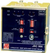
over current relay
Features Software based design DIP switch settings Choice of four curves Instantaneous high set Very low burden Application: Time graded protection of generators, Transformers, capacitors etc;
...more
Numerical Unbalance Voltage Relay JNV 026
Features Software based design Trips on neutral snap Programmable Active / Inhibit facility Programmable Rated voltages Wide range of time delay setting Principle of Operation: JNV 026 measures and displays 3 phase voltages (R,Y,B phases). It calculates percentage of unbalance voltage and if it exceeds the set unbalance voltage, the relay operates after the elapse of operating time. Under voltage fault will be detected when voltage on any phase is less than the set Under voltage limit, the relay operates after elapse of under voltage operating time. Over voltage fault is detected when voltage on any phase is more than the set Over voltage limit, the relay operates after elapse of over voltage operating time. Neutral snap will be detected when Neutral is disconnected.
...more
Numerical Transformer Differential Relay
Features Biased current differential protection Fast differential Hi-set Dual slope characteristics Inbuilt CT Ratio correction factor Adjustable 2nd harmonic restraint Adjustable 5th harmonic blocking Inbuilt Vector group compensation Two groups of settings History of 5 latest faults Principle of Operation: JND 040 provides differential protection for power transformer. The relay measures the line current of each phase from each of the windings of the transformer. Relay calculates the differential current (Id) and restraining current (Ir) per phase. The differential characteristics define the operating and the restraining regions. The shape of the characteristics defined by Initial pickup (ik), SLOPE1 (DF1), SLOPE2 (DF2) and break point (kp) are programmable. If ‘Ir’ is less than ‘kp’, then characteristics is defined by ‘DF1’ and is applicable for small differential currents. If ‘Ir’ is greater than or equal to ‘kp’, then characteristics is defined by ‘DF2’ and is applicable for large differential currents. If the operating point i.e. (Id, Ir) is within the operating region, then the relay trips. The relay provides programmable 2nd and 5th harmonic current restraint, which, exist when transformer is energized and over excitation condition exists respectively. The relay provides stability on external “line to line” and “line to ground” faults. The relay has in-built vector group compensation selection and CT ratio correction, hence the usage of external interposing CT can be avoided.
...more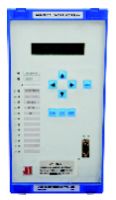
Numerical Over Flux Relay JNF 020
Application: JNF 020 Over flux relay is used in power systems in order to protect transformers and generators against insulation failure and core damage due to over heating under prolonged over fluxing condition. It protects the equipment against abnormal V/F ratios due to system disturbance which can occur during starting, load sheding and shut down conditions. Principle of Operation: Over fluxing of a transformer occurs when its flux density exceeds rated density, it is caused when its V/F ratio is greater than that which the manufacture deems it safe. This of course is the case when it is connected directly to the generator i.e, without benefit of an intervening circuitbreaker and the generator’s excitation system is energized while accelerating to operating speed JNF 020 monitors voltage & frequency ratio, when it exceeds the set value it indicates fault and the output relay operates after a set alarm time delay.
...more
Numerical Over Current Relay with Communication JNC 068 C
Features Programmable for 1A / 5A relay rating 3 OC + 1 EF + 1 SEF/REF Choice of 6 IDMT curves and definite time Trip test facility History of 6 latest faults along with settings Self supervision facility MODBUS open protocol over RS – 485 port MODBUS protocol over RS – 232 port Draw out facility with inbuilt CT shorting Standard dimension – 144mm x 144mm Principle of Operation: The relay measures the line current from each of the line CTs and if the current exceeds the set threshold, then relay extends a trip signal after an operating time. The relay's “operating time” is determined by selecting “definite time” or one of the six “inverse time” characteristics. Input to sensitive earth fault protection can be connected in two ways. First one the residual current derived from three phase current transformers, and second is low output core balance current transformer can be connected. Input to restricted earth fault protection will be derived from neutral CT output with external stabilizing resistor. Phase over current, Earth fault, Sensitive earth fault/Restricted earth fault protections* features can be made active or inhibit independently.
...more
Numerical Over Current Relay with Communication JNC 068 CALP
Features Programmable for 1A / 5A relay rating Programmable system rated frequency (50/60Hz) 3 OC + 1 EF + 1 SEF/REF Available in both Low load and normal load configurations Choice of 6 IDMT curves and definite time Trip test facility History of 6 latest faults along with settings Self supervision facility MODBUS open protocol over RS – 485 port MODBUS protocol over RS – 232 port Draw out facility with inbuilt CT shorting Standard dimension – 144mm x 144mm Principle of Operation: The relay measures the line current from each of the line CTs and if the current exceeds the set threshold, then relay extends a trip signal after an operating time. The relay's “operating time” is determined by selecting “definite time” or one of the six “inverse time” characteristics. Input to sensitive earth fault protection can be derived in two ways: Residual current derived from three phase current transformers can be used as an input Out put of core balance current transformer (CBCT) having appropriate characteristics can be used as an input. Input to high impedance restricted earth fault protection will be derived from neutral CT output with external stabilizing resistor. Phase over current, Earth fault, Sensitive earth fault/Restricted earth fault protections features can be made active or inhibit independently. Inhibition of all protection is not possible
...more
Numerical Local Breaker Backup Relay
Application: JNC 154 is a numerical local breaker backup relay. The relay is used to check the operation of feeder breaker and to trip all the breaker feeding fault in the event of feeder breaker fail to trip. Principle of Operation: The relay is designed to trip the feeder end CB if the protective relay at the distribution end operates but its corresponding CB fails to operate. The current is derived from line CT. The instantaneous trip output contact operate when the over current exist and protective relay operated. The protective relay contact (PRC) input is required. The delayed output contact operates after selected definite time.
...more
Numerical Directional Over Current Relay
Features Programmable characteristic angle Programmable operating characteristics High speed directional control Low Burden Trip test facility Choice of four inverse curve and definite time Programmable for directional / non-directional RS232 communication port RS485 communication port (optional) History of 5 latest faults Self supervision facility Principle of Operation: JNP 098/096/096P provides directional over current protection for power systems. Relay operating time is determined by selecting definite time characteristics or one of the four inverse time characteristics i.e. (3s normal inverse, 1.3s normal inverse, very inverse and extremely inverse). The operating region is defined by the characteristic angle selected. The relay measures the current and voltage from each of the phases and if the phase angle in the operating zone of the relay, then the relay extends trip signal.
...more
Numerical Current & Auto Recloser JNC 268
Features Suitable for 1A / 5A relay rating Choice of 5 IDMT curve and definite time Programmable Over current relay or Over current relay with multi shot auto re-close Trip test facility History of 6 latest faults Self supervision facility Independent trip sequence setting (IDMT / Def. time) Breaker status monitoring Standard dimension – 144mm x 144mm Disturbance records (DR) in IEEE COMTRADE format Event Records ( ER ) MODBUS open protocol over RS – 485 port MODBUS protocol over RS – 232 port Draw out facility with inbuilt CT shorting Standard dimension – 144mm x 144mm Principle of Operation: The relay measures the line current from each of the phases and if it exceeds the set threshold, then relayextends a trip signal after an operating time. The relay's operating time is determined by selecting definite time OR one of the five inverse time characteristics. Multi shot auto-re-closer facilitates automation related to closing of a breaker. Auto re-closer functionality can be programmed to provide a maximum of five shots. Dead time starts only when phase or earth fault trip occurs. After an elapse of a time interval equal to dead time, closing command will be extended. The reclaim time timer starts at the instant the dead time timer expires. If, after extending the “breaker close” signal an over current fault was detected before the reclaim time timer reached its terminal count, then the relay understands that the fault in the system is still persisting and the over current relay will issue a trip signal. The relay tries to close the breaker for a maximum of the programmed number of shots beforeit choses to lockout.
...more
Neutral Unbalance Current Relay
Application: Neutral unbalance current protection of double star capacitor banks with floating neutral. Principle of Operation: The sensing current is converted to voltage by an internal resistor and this voltage is fed to a harmonic network which is tuned to the fundamental frequency. The output of filter is fed to a voltage comparator. When the sensing current signal at the fundamental frequency exceeds the set value, the comparator gates a train of pulses to the processor. The program residing in the CPU performs the function of control and also gives output signals for relay and LED driver circuits. The operation of the relay is indicated by the glowing of a 'Red' LED,which has to be reset manually by means of a 'RESET' push button provided on the front of the relay. A 'Trip Test' push button is also provided in the relay to enable testing of the trip and alarm circuits. When this push button is pressed,the output element of the relay is energized and its contacts close to energize the trip and alarm circuits.
...more
Motor protection relay
Features Software based design ‘Block on Start’ feature provides very accurate overload protection Definite time over load protection Locked rotor current protection Single phasing protection Wide setting ranges Draw -out case Principle of Operation: This is a Microprocessor based relay which has been designed to sense the load currents in all the three phases of an AC motor. It monitors the levels of these currents continuously, giving output signals for relay and LED driver circuits.
...more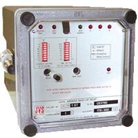
Local Breaker Backup Relay
Application: JRC 154 local breaker backup relay, is used to check the operation of distribution end circuit breakers and to trip the feeder end circuit breaker if the distribution end circuit breaker fails to trip. Principle of Operation: If a fault occurs at the distribution end and the respective protective relay operates but the corresponding CB fails to operate then the system may have to face catastrophic consequences. JRC-154 is a instantaneous and definite time over current relay that also monitors the non-potential contacts of the downstream protective relays. The relay is designed to trip the feeder end CB if the protective relay at the distribution end operates but its corresponding CB fails to operate.
...more
Lead Power Factor Relay
1 - 11,583 Per Piece
Features Software based design Display of Power factor, Phase angle and frequency Dust proof enclosure Draw out type Principle of Operation: The R-Phase line current input to the relay is derived from the line CT. The R – B line voltage is scaled to relay rated voltage using transformers. The relay measures the phase angle between R-Current and R-B voltage. The output contact operates when PF reaches lead condition after fixed operating time of 60s. The output contact, release when PF reaches lag condition after fixed operating delay of 60s. The aux supply required for the operation of relay is derived from the voltage input hence no need of dedicated power source. The relay displays power factor, line frequency, phase angle between line current and voltage.
...more
Inverse Time Current Relay
Features Software based design Programmable time current characteristics Choice of four curves Wide setting ranges Draw - out case Principle of Operation: The relay measures the line current from each of the phases and if it exceeds the set threshold, then the relay extends a trip signal after an operating time. The relay's operating time is determined by selecting one of the four inverse time characteristics. The relay has facility to active / inhibit the high set protection feature. The relay output contacts are self reset / Hand reset type. Relay operation without any fault current can be test facility.
...more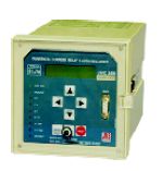
Feeder Protection Relay
Features Suitable for 1A / 5A relay rating Choice of 6 IDMT curve and definite time History of 6 latest faults along with settings Self supervision facility Breaker status monitoring In-built breaker trip circuit supervision Disturbance records (DR) in IEEE COMTRADE format – Optional Event Records (ER) – Optional Programmable digital inputs and outputs MODBUS open protocol over RS – 485 port MODBUS protocol over RS – 232 port Draw out facility with inbuilt CT shorting Principle of Operation: JNC 268 N / JNC 268 A / JNC 268 L : The relay measures the line current from each of the line CTs and if the current exceeds the set threshold, then relay extends a trip signal after an operating time. The relay's “operating time” is determined by selecting “definite time” or one of the six “inverse time” characteristics. A sensitive earth fault or restricted earth fault (suitable for high impedence REF scheme) is provided in the relay.The input to sensitive earth fault protection can be connected in two ways. First one the residual current derived from three phase current transformers, and second is low output core balance current transformer can be connected. The input to restricted earth fault protection will be derived from neutral CT output with external stabilizing resistor.The relay has facility to monitor circuit breaker operation through 52a or 52b aux contacts of circuit breaker. 4 programmable digital inputs (PDI) and 4 programmable digital outputs are provided and can be used to synthesize logic along with some internal digital inputs i.e.(phase OC pickup, Earth fault pickup, Phase high set trip, Earth fault OC trip, Earth fault high set trip,etc). Together, this feature can be effectively used to reduce the number of aux. tripping relays in a protection scheme. The trip relay (B1-B2) can be operated either when any one / more of the protection scheme provided inside JNC 268 x initiates the relay or any/more of the PDI initiates the same relay. Each PDO has independent timer. Each PDI has programmable mask facility.The relay in-built breaker trip circuit supervision and dedicated alarm contact to indicate trip circuit failure. JNC 268 A : Provides Multi shot auto re-closer facilitates automation of breaker operation. Auto re-closer can be programmed to provide a maximum of five shots. “Dead time” starts when a trip signal is provided due to the occurrence of a fault involving L-L or L-G or L-L-G or L-L-L or L-L-L-G. After an elapse of a time interval equal to “dead time”, closing command will be extended. The “reclaim time” timer starts at the instant when the “dead time” timer expires. If after extending the “breaker close” signal an over current fault was detected before the “reclaim time” timer reached its terminal count, then the relay understands that the fault in the system is still persisting and the over current relay will issue a trip signal. The relay tries to close the breaker for a maximum of the programmed number of shots before it choses to lockout. The relay can be configured for independent trip sequence as IDMT or Def. time JNC 268 L : The relay monitors line current even after the trip condition to ensure breaker operation. Even if small current exist in the line the relay sends trip command to adjacent or backup breaker after definite operating time. The current threshold and definite time required to detect breaker failure are programmable.
...more
Definite Time Single Pole Over Current Relay
Features Software based design Wide auxiliary supply Low burden Principle of Operation: JRC 932 provides earth fault protection for power systems. Relay operating time is determined by the set definite time. The relay measures the current from the input CT and if it exceeds the set threshold, it extends a trip signal after the operating time, which is determined by set definite time. The relay output contacts are self reset type. TEST button facilitates the testing of relay contacts for the trip and alarm circuits.
...more
Definite Time Earth Leakage Relay
100 - 19,219 Per
1 Piece (MOQ)
Features Bar graph indication of leakage current Remote reset and test facility Wide range of settings Low burden Principle of Operation: JRC 974 provides earth leakage protection for power systems. The relay operating time is determined by a programmable definite time delay. The relay measures the earth leakage current from the CBCT and if it exceeds the set threshold, it extends a trip signal after the operating time. The relay output contacts are self reset type. TEST button facilitates verification of relay contacts.
...moreBe first to Rate
Rate ThisOpening Hours
Share your Correspondence Details to receive messages from JVS Electronics Pvt Ltd.