PCB Single Side boards
Single-sided PCB means that wiring is available only on one side of the insulating substrate. The side which contains the circuit pattern is called the solder side whereas the other side is called the component side.These types of boards are mostly used in case of simple circuitry and where the manufacturing costs are to be kept at a minimum. Nevertheless, they represent a large volume of printed boards currently produced for professional and non-professional grades. The single-sided boards are manufactured mostly by the print and etch method or by the diecut technique by using a die that carries an image of the wiring pattern; and the die is either photoengraved or machine-engraved.Normally, components are used to jump over conductor tracks, but if this is not possible, jumper wires are used. The number of jumper wires on a board cannot be accepted beyond a small number because of economic reasons, resulting in the requirement for double-sided boards.
...more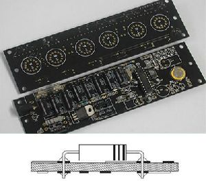
PCB Double Side Board
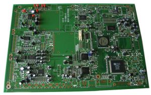
Double-sided printed circuit boards have wiring patterns on both sides of the insulating material, i.e. the circuit pattern is available both on the components side and the solder side. Obviously, the component density and the conductor lines are higher than the single-sided boards. Double-sided board with plated through-hole connection (PTH) Double-sided board without plated through-hole connection (non-PTH) Double-sided PTH board has circuitry on both sides of an insulating substrate, which is connected by metallizing the wall of a hole in the substrate that intersects the circuitry on both sides. This technology, which is the basis for most printed circuits produced, is becoming popular in cases where the circuit complexity and density is high. Double-sided non-PTH board is only an extension of a single-sided board. Its cost is considerably lower because plating can be avoided. In this case, through contacts are made by soldering the component leads on both sides of the board, wherever required. In the layout design of such boards, the number of solder joints on the component side should be kept to a minimum to facilitate component removal, if required. It is generally recommended that conductors should be realized as much as possible on the non-component side and only the remaining should be placed on the component side.
...more
Multilayer Pcb Board
A multilayer PCB board is used in situations where the density of connections needed is too high to be handled by two layers or where there are other reasons such as accurate control of line impedances or for earth screening. A multilayer PCB contains two reference planes and a signal via. The signal via allows a signal to flow through all the planes. A stitching via is connected to one of the planes next to the signal via and serves to reduce the area through which the signal passes through. This is very important as it may assist in reducing noise and cross talk. The electrical circuit is completed by interconnecting the different layers with plated through-holes, placed transverse to the board at appropriate places. Multi-layer boards have three or more circuit layers, while some boards have even as many as 50 layers. Advantages of multilayer PCBs include high reliability and uniform wiring. However, the initial costs are higher than that of one-layered PCBs. Also, repairing a multilayer PCB is quite difficult. Wherever weight and volume savings in interconnections are the overriding considerations When the complexity of interconnection in sub-systems requires complicated and expensive wiring or harnessing When frequency requirements call for careful control and uniformity of conductor wave impedances with minimum distortions and signal propagation, and where the uniformity of these characteristics from board-to-board is important When coupling or shielding of a large number of connections is necessary With multilayers, all interconnections can be placed on internal layers, and a heat sink of thick solid copper can be placed on the outer surfaces.
...more
Multilayer PCB
A multilayer PCB board is used in situations where the density of connections needed is too high to be handled by two layers or where there are other reasons such as accurate control of line impedances or for earth screening. A multilayer PCB contains two reference planes and a signal via. The signal via allows a signal to flow through all the planes. A stitching via is connected to one of the planes next to the signal via and serves to reduce the area through which the signal passes through. This is very important as it may assist in reducing noise and cross talk.
...more
Metal Core PCB
As Metal Core PCB means the base material for PCB is metal, but not normal FR4CEM1-3, etc, and currently what the metal used are Aluminum, Copper alloy. MCPCBs are used instead of traditional FR4 or CEM3 PCBs because of the ability to efficiently dissipate heat away from the components. This is achieved by using a Thermally Conductive Dielectric Layer. The main difference between a FR4 board and MCPCB is the thermally conductive dielectric material in the MCPCB. This acts as a thermal bridge between the IC components and metal backing plate. Heat is conducted from the package through the metal core to an additional heat sink. On the FR4 board the heat remains stagnant if not transferred by a topical heatsink. According to Avago’s white paper a MCPCB with a 1W LED remained near an ambient of 25C, while the same 1W LED on a FR4 board reached 12C over ambient.
...more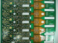
flexible printed circuits
Flexible electronics, also known as flex circuits, is a technology for assembling electronic circuits by mounting electronic devices on flexible plastic substrates, such as polyimide and PEEK Film. Additionally, flex circuits can be screen printed silver circuits on polyester. Flexible electronic assemblies may be manufactured using identical components used for rigid printed circuit boards, allowing the board to conform to a desired shape, or to flex during its use. These flexible printed circuits (FPC) are made with a photolithographic technology.
Thickness : 0.05 mm
...more
Flexible electronics board
Flexible electronics, also known as flex circuits, is a technology for assembling electronic circuits by mounting electronic devices on flexible plastic substrates, such as polyimide and PEEK Film. Additionally, flex circuits can be screen printed silver circuits on polyester. Flexible electronic assemblies may be manufactured using identical components used for rigid printed circuit boards, allowing the board to conform to a desired shape, or to flex during its use. These flexible printed circuits (FPC) are made with a photolithographic technology. An alternative way of making flexible foil circuits (FFCs) is laminating very thin (0.07 mm) copper strips in between two layers of PET. These PET layers, typically 0.05 mm thick, are coated with an adhesive which is thermosetting, and will be activated during the lamination process. FPCs and FFCs have several advantages in many applications: Tightly assembled electronic packages, where electrical connections are required in 3 axes, such as cameras (static application). Electrical connections where the assembly is required to flex during its normal use, such as folding cell phones (dynamic application). Electrical connections between sub-assemblies to replace wire harnesses, which are heavier and bulkier, such as in cars, rockets and satellites . Electrical connections where board thickness or space constraints are driving factors.
...more
electronic print board
Single-sided PCB means that wiring is available only on one side of the insulating substrate. The side which contains the circuit pattern is called the solder side whereas the other side is called the component side. These types of boards are mostly used in case of simple circuitry and where the manufacturing costs are to be kept at a minimum. Nevertheless, they represent a large volume of printed boards currently produced for professional and non-professional grades. The single-sided boards are manufactured mostly by the print and etch method or by the diecut technique by using a die that carries an image of the wiring pattern; and the die is either photoengraved or machine-engraved.
...more
Double sided PCB
Double-sided printed circuit boards have wiring patterns on both sides of the insulating material, i.e. the circuit pattern is available both on the components side and the solder side. Obviously, the component density and the conductor lines are higher than the single-sided boards. Double-sided PTH board has circuitry on both sides of an insulating substrate, which is connected by metallizing the wall of a hole in the substrate that intersects the circuitry on both sides. This technology, which is the basis for most printed circuits produced, is becoming popular in cases where the circuit complexity and density is high.
...more
Printed Circuit Boards
Be first to Rate
Rate ThisOpening Hours
Share your Correspondence Details to receive messages from Electro Track