Worm Reduction Gear

Worm Gears
The specialty of a worm gear and worm wheel is that they provide a large speed ratio but with significant sliding. Another feature being of the worm gear is that most of the designs are non reversible. Worm Gears are suited for right angle skew shafts, high velocity ratio , higher speeds and loads. Although worm gears can be standardized for high precision, they have their own limitations. Worm Gears can be at best considered for average precision meshes, but for works of high precision they have to be selected with care. They are probably the apt choice for a combination of high velocity ratio and right angle drive. Excellent lubrication should always be ensured in use of worm gears since high sliding requires ,lubrication at all times.
...more
textile spares

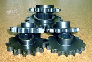
Sprockets
Chain Drive: Chain drives are used where positive action is required. The velocity is constant to some extent. Power is transmitted, in this case over a shorter distance than in the case of belt or rope drives. Chains are made up of rigid links and of various types. They are classified as: Hoisting chains Conveying or elevating chains. Power transmission chains. The wheels over which chain runs are called sprocket wheels. These wheels have projecting teeth which fit the suitable recess in the links of the chain and thus enable a positive drive to be obtained. The pitch of the chain is defined as the distance between a hinge center of one link to the corresponding hinge center of the adjacent link. The pitch circle diameter of the chain sprocket is the diameter of the circle on which the hinge centers lie, when the chain is wrapped round the sprocket. Quality: Sources of errors in manufacturing gears:The gears (gear teeth) are generally made by one of the following two methods: Reproducing method , in which the cutting tool is formed involute cutter ,which forms the gear teeth profiles by reproducing the shape of the cutter itself. In this method, each tooth space is cut independently of the other tooth spaces. Generating method, in which the cutting tool (hob forms) the profiles of several teeth simultaneously during constant relative motion of the tool and bank. The various sources of errors in the gear made by reproducing method can be due to incorrect profile on the cutting tool, incorrect positioning of the tool in relation to the work and incorrect indexing of the blank The sources of error when gears are made by generating method are: Errors in the manufacture of the cutting tool Errors in positioning the tool in relation to the work and Errors in the relative motion of the tool and the blank during the generating operation.
...more
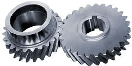
Helical Gears

Bevel gears
Why use a bevel gearbox?A bevel gearbox has an advantage over the worm gear because its efficiency is much higher. Yet another advantage being bevel gears is that bevel gears gives Bevel Gearsyou the flexibility of right angle solution at a lower ratio. For shafts whose axes intersect straight bevel gears are best suited. They also perform admirably under high speeds and high loads. As mentioned earlier they are the apt choice for right-angle drive particularly low ratios. Nevertheless their complicated tooth form and fabrication limits precision. The ratio of a helical or bevel gear set is simply by the number of teeth in the larger gear divided by the number of teeth in the smaller gear. For example, a gear set with 36 teeth in the larger gear and 12 teeth in the smaller gear has 3:1 ratio. Prakash bevel gears are renowned in the market. Please contact us for all your tailor made needs. Application of Bevel: Bevel and hypoid gears may be used to transmit power between shafts at practically any angle and speed. The particular type of gearing best suited for specific job, however depends on the mounting and the operating conditions. Straight and Zerol Bevel gears: For peripheral speeds upto 1000 feet per minute, where maximum smoothness and quietness are not primary considerations, straight and Zerol bevel gears are recommended.For such applications, plain bearings may be used for radial and axial loads, although the use of anti-friction bearings are always preferable. Plain bearings permit a more compact and less expensive design; one reason why straight and Zerol bevel gears are much used in differentials. This type of bevel gearing is the simplest to calculate and set up for cutting, and is ideal for small lots where fixed charges must be kept to a minimum. Zerol bevel gears are recommended for use in place of straight bevel gears: Where hardened gears of high accuracy are required ,since zerol gears may be ground ; and When only spiral type equipment is available for cutting bevel gears. Spiral Bevel and hypoid gears: Spiral bevel and hypoid gears are recommended for applications where peripheral speeds exceed 1000 feet per minute or 1000 revolutions per minute, whichever occurs first .In many instances they may be used to advantage at lower speeds, particularly where extreme smoothness and quietness are desired. For peripheral speeds above 8000 feet per minute, ground gears should be used. For large reduction ratios the use of spiral an hypoid gears will reduce the overall size of installation since continuous pitch in contact of these gears makes it practical to obtain smooth performance with smaller number of teeth in the pinion than is possible with straight or Zerol bevel gears. Hypoid gears are recommended for industrial applications: When maximum smoothness of operation is desired; for high reduction ratios where compactness of design, smoothness of operation, and maximum pinion strength are important; for non-intersecting shafts. Bevel and hypoid gears may be used for both speed-reducing and speed-increasing drives. In speed-increasing drives, however the ratio should be kept as low as possible and the pinion mounted on anti-friction bearings; otherwise bearing friction will cause the drive to lock. Types of Bevel Gears: Bevel gears are conical gears, that is ,gears in the shape of cones, and are used to connect shafts having intersecting axes. Hypoid gears are similar in general form to bevel but operate on axes that are offset, straight-tooth type or of the curved toot type. The latter type includes spiral bevels, Zerol bevels, and hypoid bevels. The following is a brief description of the distinguishing characteristics of the different types of bevel gears. Straight bevel gears: The teeth of this most commonly used type of bevel gear are straight but their sides are tapered so that they would intersect the axis at a common point called pitch cone apex if extended inward. The face cone elements of most straight bevel gears, however are now made parallel to the root cone elements of mating gear to obtain uniform clearance along the length of the point inside the pitch cone. Straight bevel gears are easiest to calculate and are economical to produce. Straight bevel gear teeth may be generated for full length contact or for localized contact. The latter are slightly convex in length wide direction so that some adjustment of the gears during assembly is possible and small displacements due to load reflections can occur without undesirable load concentration o the ends of the teeth. This slight lengthwise rounding of the tooth sides need not be computed in te design but is taken care of automatically in the cutting operation on the newer types of bevel gear generators. Zerol Bevel Gears: The teeth of Zerol bevel gears are curved but lie in the same general direction as teeth of straight bevel gears. They may be thought of as spiral bevel gears of zero spiral angle and are manufactured on the same machines as spiral bevel gears. The face cone elements of Zerol bevel gears do not pass through the pitch cone apex but instead are approximately parallel to the root cone elements of the mating gear to provide uniform tooth clearance.The root cone elements also do not pass through the pitch cone apex because of the manner in which these gears are cut. Zerol bevel gears are used in place of straight bevel gears when generating equipment of the spiral-type but not the straight type is available, and may be used when hardened bevel gears of high accuracy(produced by grinding) are required. Spiral Bevel Gears: Spiral bevel gears have curved oblique teeth on which contact begins gradually and continues smoothly from end to end. They mesh with a rolling contact similar to straight bevel gears. As a result of their overlapping tooth action, however, spiral bevel gears will transmit motion more smoothly than straight bevel or Zerol bevel gears, reducing noise and vibration which become especially noticeable at high speeds. One of the advantages associated with spiral bevel gears is the complete control of the localized tooth contact. By making a slight change in the radii of curvature of the mating tooth surfaces, the amount of surface over which tooth contact takes place can be changed to suit the specific requirements of each job. Localised tooth contact promotes smooth, quiet running spiral bevel gears and permits some mounting deflections without concentrating the load dangerously near either end of the tooth .Permissible deflections established by experience are given under the heading “Mountings for Bevel Gears”.
...moreBe first to Rate
Rate ThisOpening Hours