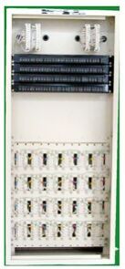
VF TRANSFORMER BAY
The V.F Transformer Bay manufactured by EPSILON is used in the communication line of Railway Electrification area to ensure systematic installation of V.F Transformers for use in various circuits. The V.F Transformer Bay houses up to 54 Transformers. All the Types of Transformers, namely V.F Tapping, Terminating and Signalling Transformers are housed in this Bay as per the requirements in the Circuit. Krone Type Connectors are provided for Wiring Incoming / Outgoing Cables. Link Panels are used for establishing Isolation / Connection on the lines in the Section. Integrated Line Protection Circuits are provided for each Quad. The Bay is constructed out of M.S. Steel Sheets complete with 5 Rows of Link Panels, Aluminum Sections for mounting the transformer and copper earthing strip. It is of sturdy construction and ensures compactness. The doors are made with reinforcement to avoid tilt. Grommets are provided for cable entries. Copper Strip is provided for earthing. Link Panels are as per ITI Specifications DE 224008/A. Links as per ITI Spec. No. BL/57279 are also supplied along with the Bay. Brackets are also provided for cable harnessing. WEIGHT : 75 Kgs. (Approx.) for all Quads DIMENSIONS AND WEIGHTS : Shall vary as per Number of Quads
...more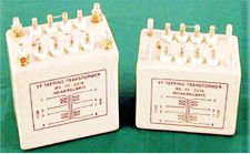
Termination Transformers
The Voice Frequency and V.F Signalling Transformers manufactured by Epsilon are used for derivation and termination of Underground Telecommunication Cable Circuits. The Side Circuits of the paper insulated V.F Quads, which are loaded are used for the transmission of Speech of the unloaded phantom for derivation and termination of Underground Telecommunication Cable Circuits. The side circuits are used for transmission of interrupted 50 Hz rising current for Signaling. The Transformers are manufactured in four types as follows :- V.F. Transformer for loaded V.F. Side Circuits, Impedance Ratio 1120 : 1120 ohms. V.F. Terminating Transformer for unloaded V.F. Side Circuits (P.E. Insulated Quads) Impedance Ratio 470 : 1120 ohms. V.F. Transformer for inter wire Telegraph loaded V.F. Side Circuits, Impedance Ratio 1120 : 600 ohms. Other Impedance Ratio are also available on request, such as 470 : 470, 470 : 600, 600 : 600. Each Transformer is housed in the metallic case filled with insulating compound and is hermetically sealed, to withstand extreme weather conditions. Terminals are taken out on the top of the transformer case through proper feed through terminals.
...more
telephone accessories
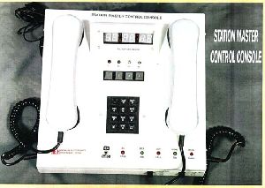
Station Master Control Console
The Station Master uses several Telephones for different communications for the purpose of smooth Train Traffic Movement in a Station. Practically, it becomes tedious to attend to the Telephones spread over the Station Master’s Table.The Station Master Control Console using Micro Controller, designed and developed by EPSILON enables easy and convenient operations by the Station Master / Assistant Station Master.This Unit enables communication in : A. 4 WIRE MODE (IRS:TC-60/2007)I Section ControllerII Traction Power ControllerIII Traction Loco ControllerIV Other Controllerby pressing the designated Push Button Switch out of the 4 Controllers. B. 2 WIRE MODE (IRS:TC-80/2000) OR (IRS:TC-79/2000)For Point to Point Communication between:(i) Station Master & Assistant Station Master(ii) Station Master / Assistant Station Master and LC Gate(iii) Station Master / Assistant Station Master and Yard/ Maintenance etc.A 4 x 3 matrix keypad is provided for selecting the required Slave. C. AUTO MODEKeep the Push Button Switch provided on the Front Panel for selecting the BSNL or RLY. The Station Master also can talk to Auto Telephone Railway and DOT by pressing the Push Button marked RLY/DOT and provided on the Front Panel and by dialing the desired number.When a Call is received from any Auto Telephone, the respective LED shall glow. The Station Master can press the respective Push Button Switch and attend the Call.The Unit shall consists of the following :1. One Handset with Press to Talk (PTT) Switch to be used only in 4 Wire Mode, kept on the left hand side of the unit. Another Handset for use with 2 Wire Intercom or Auto Telephones kept on the right hand side of the unit.2. Cradle Switches.3. 4 Nos. of Push Button Keys for Communication between Station Master and Controllers marked CONTROL I to CONTROL IV with LED indication provided beside.4. 5 Nos. of DC Buzzers and 2 Nos. of AC Ringers.5. Keypad (3 x 4 matrix) for the Selective Calling Telephone and Auto Telephone.6. A Push Button Switch to select 2 Wire Intercom or Auto Telephone.7. Two Push Button Switches for connecting to Auto Telephone. Two LEDs by the side of this Switch indicates connection to Auto Telephone.8. A Push Button Switch to select up or down.9. A Ringer Circuit with Ringer for ringing in case the Station Master is called on the Auto Telephone. OPERATION :4 WIRE MODE :The Station Master can call any of the 4 Controllers by pressing the assigned Push Button (Enabling) and by pressing the Press to Talk Switch in the handset, the Station Master can converse with the called Controller. After conversation, he can press the same Push Button Switch again to disconnect (Disabling). Similarly when a Controller calls the Station Master, the designated LED shall flash and the Buzzer shall hoot. The Station Master has to press the called Push Button Switch to receive the Call, the Buzzer shall stop, LED shall change from flash to steady. Press the Press to Talk Switch and the conversation shall be through.At a time only one Controller can talk to the Station Master.When another Controller calls the Station Master, when the Station Master is already in conversation with the first Controller, the Caller’s LED shall flash and the buzzer shall hoot. The Calling Controller shall get the ring back tone. In case the Station Master feels that the call of the Second Controller is important, he should press the Push Button of the first Caller to disable and then press the Calling Controller’s Push Button Switch for communication. After the conversation the same Push Button shall be pressed again for disabling. Similarly the Station Master can have communication with any of the 4 Controllers, using only one Telephone Handset.The 6 Wires coming from the 4 Nos. of 4 Wire Decoders are terminated inside the Unit as per the Standard Wiring for Cradle Switch /+12, -12V / MIC / REC / BUZ / PTT / LED.Thus this Unit replaces 4 Control Telephones as per IRS:TC-38/97.2 WIRE MODE : Press the Push Button Switch to 2 WIREThe functions are same as Desk Type 2 Wire / 12 Way Selective Calling Telephone as per IRS:TC-80/2000 or Electronic Magneto Telephone as per IRS:TC-79/2000. In this case the Press to Talk Switch need not be pressed for talking. However after conversation the Handset should be kept on the ‘Cradle to disconnect or press the Cradle Switch manually to disconnect’. The LED provided and a Buzzer shall be activated when any of the Slave Telephone calls the Station Master. Press * for Selective Calling or Press # for Magneto. AUTO MODE :Whether the Push Button Switch is in AUTO Mode and when the Push Button Switch marked RLY or DOT is pressed, the Station Master gets connected to the respective Auto Telephone. AC Ringer and an LED provided in the Unit shall ring and the LED shall glow whenever there is a Call from the Auto Telephone. To attend the Call, the Station Master has to press the Push Button Switch marked ‘AUTO’. After the conversation, the Station Master has to press the Push Button Switch again to normal position. In case the Station Master wants to call any Auto Telephones, he has to press the Push Button Switch marked RLY or DOT and dial the desired number using the Keypad Switch. He can set the Push Button Switch to 2 Wire or Auto Mode as per the requirement.FOR BETTER CONVENIENCE OF OPERATION, OUR FINAL DESIGN IS IN 2 PARTS FOR 4 WIRE AND 2 WIRE AND AUTO MODES.D. DIGITAL CLOCK - 6 Digit LED Type RTC/GPS Based.This shall indicate the time based on Real Time or GPS.The Station Master Control Console works on 12VDC and the maximum current consumption shall be 600m Amps.As per latest version, the 2 WIRE MODE is kept as a separate unit with UP and DOWN Calling Indication.
...more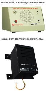
SIGNAL POST TELEPHONE
The Signal Post Telephone (SPT) consists of : Master Telephone in Assistant Station Master’s Cabin (MT) Slave Telephone fixed on Signal Post (ST) SCOPE : This is similar to the above, but due to heavy induction in the cable due to 25KV AC overhead lines, it has separate Power Supply with the Slave (24VDC) and it has specially designed filter to remove the induced voltage in the cable. MASTER TELEPHONE (MT) : This is kept on the Desk of the ASM to facilitate communication between ASM (MT) and the loco driver (ST) for controlling movement of train. This consists of a Microphone Amplifier, Loud Speaker and a Press To Talk Switch. The Master (MT) and the Slave (ST) have separate power supplies of 24VDC each. Provision is given on the front panel to adjust the output level by using a Potentiometer.
...more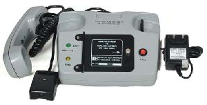
Push Button Magneto Telephone
This Push Button Magneto Telephone is similar to the Rotating Type Magneto Telephone, but the Ring Generator is Electronic and appears across the Lines as along as the ‘Press To Call’ (PTC) button is pressed.It works on 6VDC supply from 6V, 1.2 AH Ni-Mh Battery provided inside and a charger working on 100 - 300VAC, 50 Hz. Provision is given in the Rosette Box to connect external 6VDC SCOPE :The Push Button Magneto Telephone Model MTI 201 is used for Point to Point Communication for a distance of 10 Kms., when the diameter of copper conductor is 1.5 mm Sq.CONSTRUCTION :The Telephone is Desk Type, housed in ABS (Acrylonitrile Butadiene Styrene) Plastic Moulded Body (Cover and Base) and Handset.It has Electro Dynamic Transducers for Transmitter and Receiver.It has Coiled Cord and Straight Cord, a Rosette Box for connecting Line and external Power Supply (if required).The Ring Generator, Ringer, Induction Coil and other Speech Circuitry are wired in a PCB of 1.6mm thick FRP Printed Circuit Board. A standard hook (Cradle) Switch provided disconnects the incoming Ringing Voltage when lifted. To call the handset has to be on the hook.A Press to Call (PTC) Switch is provided on the top for Calling and a Press to Talk (PTT) Switch is provided in the handset.TECHNICAL :(1) Ring Generator :Frequency : 25 ± 5HzOutput : 60VAC max.(2) Speech :Tx : 0dB across LinesRx : -12dBPOWER SUPPLY :The Telephone works on 6V DC supply from a 6V, 1.2 AH Ni-MH Battery provided inside.A Socket is provided at the back of the Telephone Body to connect a charger working on 100-300VAC, 50Hz. A hinged metal door is provided on the top of the Telephone to replace the Battery as and when required. The external voltage connection provided in the Rosette Box can accept a maximum of 6V DC only.CONSUMPTION :Idle : 3mAConversation : 15mARinging : 300mAINSTALLATION(1) Open the Rosette Box and connect L1, L2 between one phone and the other.(2) Open the cover of each Battery Box on top cover and slide on ‘ON’ the Switch provided inside the compartment.(3) The Power ON LED shall glow. Replace the cover.(4) Press the Call Button and ensure that the other phone is ringing. All this time, the calling handset has to be on the hook.(5) The Charger can be connected as and when the Battery Voltage is low. The Charger has a LED which goes off when the Battery is fully Charged.
...more
impedance matching transformers
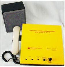
EMERGENCY CONTROL ROOM EQUIPMENT
This Equipment is also an associated unit with the Test Room Equipment. The Control Room Equipment (IRS:TC:60/2007) can be supplied duly modified to do the functions of the Emergency Control Room Equipment. All Controls are provided in the Table Top Equipment and the Loud Speaker Unit is kept separately. WEIGHT : 15.0 Kg. (Approx.)
...more
electronic modules
Cable Termination Box
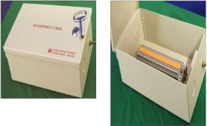
The Cable Termination Box can be supplied for 5 - 20 Pairs as per the requirement. The Box is rugged, weatherproof, and highly reliable and uses Universal Test Disconnect Terminal Blocks of PHOENIX OR WAGO Make
...more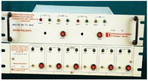
AUTOMATIC RADIO PATCHING UNIT
Automatic Radio Patching System for Control / Far Ends using DTMF Signalling for OFC System with Dedicated / Without Dedicated Channels. Control End Relay kept in Control Office Works on 12V DC and the Distance End Relay kept in the OFC Building works on 48V DC. This unit is optionally available for Control End / Far End with or without 4 Way Branching Network. WEIGHT : 12.0 Kg. (Approx.)
...more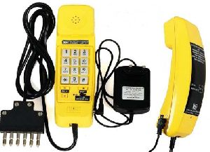
auto dialling system
As per the Specification Clause No: 3.0 The Way Side Telephone consists of Desk Type Telephone Power Supply-Cum-Charger M.F. Battery of 12V, 7AH 6 Pin Plug Assembled in a Wooden Box and this weights over 7.5 Kgms. As per the field user’s report it is too heavy to carry and they expressed that this should be of light weight. Keeping Customer Satisfaction on priority our R & D team developed a Light Weight Telephone working on 3Vdc with a Lithium-Iron Battery of 3.6Vdc, 900 mAH with a suitable Charger working on 100-300VAC, 50Hz. The Battery can be used for 20 hours continuously on full charge. The performance of the Samples are tested and found to be meeting all the parameters as per the above Specification. The weight is around 900 gms. including the Charger, 6 Pin Plug and carrying Pouch
...more
Power Supplies

Battery Chargers

fail safe timers

flashers

gps clocks

telecom bays

Sub Assemblies
Be first to Rate
Rate ThisOpening Hours