
ZEZ SILKO Make Power Capacitors
We offer Zez Silko Make Power Capacitors. Power Factor Correction Capacitors: Cylindrical,MKP type,N2 Gas filled Capacitors Life expectancy :1,50,000-2,00,000 Hours Power Losses : 0.2WattsKVAR Inrush Current : 400X In Rated Voltage : 230V-800V
...more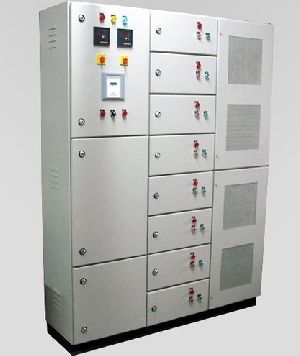
RPFC Panel
We are offering apfc panels benefits avoid penalty long life of switch gear components maximize output efficiency reduce md kva reduce kwh consumption eb bill low maintenance of your plant equipments.
...more
Power Factor Improvement Capacitors
1 Piece(s) (MOQ)
We are offering PFC Capacitors
Brand Name : EPCOS Make
Certification : ISI
Operating Temperature : Class D
Usage : Power Factor Application
Voltage : 440V
...more
Power Factor Correction Capacitor
1 Piece(s) (MOQ)
Power Factor correction Capacitors
Brand Name : EPCOS Make
Certification : ISI
Operating Temperature : Class D
Usage : Power Factor Application
Voltage : 400V,415V,440V,525V & 690V
...more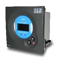
power factor control relay
We are offering power factor control relay. Functions: pfr 06pfr 12 is the new range of power factor regulators using on the highest technology and designed for easy and effective regulation. Regulator monitors the power system status and accurately and quickly takes decisions on the connection or disconnection of compensation stages in order to reach the preset target cos phi. Regulator´s microprocessor records system voltage and current consumption of the entire operation via instrument transformer inputs and uses these to calculate the relationship between active power and reactive power in the power system. Regulator calculates the basic harmonic factor of the active and reactive currents using the fft algorithm. Thus precise measurement and control are provided even if the current waveform is distorted by higher harmonic components. Benefits 6 or 12 steps thd measurement alarm output 4 quadrant pfc fcp system (fast computerized program), minimizes the number of onoff operations measuring cos phi, using true rms voltage and current values displays all measurements on one single display connected steps display features designed for easy and intuitive handling by the user parameter setting in run−time totally digital setting and handling technical data supply and measuring voltage: 400 vac (+15−10%), 45−65 hz current measurement circuit: ct, in 5 accuracy of current measurement: 1% accuracy of voltage measurement: 1% accuracy of cos phi measurement: +− 2%, 1 digit display: 1 line x 3 digits x 7 segments + 20 display icons output: relays, max. 250 v, 4 a, ac1 protection degree: ip 55, category iii dimensions: 144 x 144 x 62 mm
...more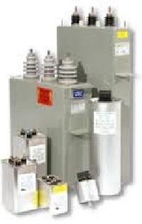
Power Factor Capacitor

3 Phase Power Capacitor
1 Piece(s) (MOQ)
We are offering power capacitor. 3 phase power factor correction capacitors voltage range: 400v,415v,440v,460v,525v,690v kvar range: 1 kvar - 30 kvar inrush current: 400xin life expectancy:1,50,000-2,00,000 mounting position:any mounting:stud m12 at the bottom case:aluminium dielectric: mkp - metallized pp film impregnant: dry type, inert gas discharge resistors:included - 50 v, 1 minute
Country of Origin : India
Type : Three Phase Power Analyzer
Certification : CE Certified
Condition : New
Automatic Grade : Automatic
...more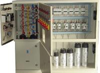
apfc system
We are offering apfc system. Automatic power factor correction what is power factor? power factor definition: power factor is the ratio between the kw and the kva drawn by an electrical load where the kw is the actual load power and the kva is the apparent load power. It is a measure of how effectively the current is being converted into useful work output and more particularly is a good indicator of the effect of the load current on the efficiency of the supply system. all current flow causes losses both in the supply and distribution system. A load with a power factor of 1.0 results in the most efficient loading of the supply. A load with a power factor of, say, 0.8, results in much higher losses in the supply system and a higher bill for the consumer. A comparatively small improvement in power factor can bring about a significant reduction in losses since losses are proportional to the square of the current. when the power factor is less than one the ‘missing’ power is known as reactive power which unfortunately is necessary to provide a magnetizing field required by motors and other inductive loads to perform their desired functions. Reactive power can also be interpreted as wattles, magnetizing or wasted power and it represents an extra burden on the electricity supply system and on the consumer’s bill. a poor power factor is usually the result of a significant phase difference between the voltage and current at the load terminals, or it can be due to a high harmonic content or a distorted current waveform. a poor power factor is generally the result of an inductive load such as an induction motor, a power transformer, and ballast in a luminary, a welding set or an induction furnace. A distorted current waveform can be the result of a rectifier, an inverter, a variable speed drive, a switched mode power supply, discharge lighting or other electronic loads.
...more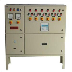
apfc system
We are offering apfc system. Automatic power factor correction what is power factor? power factor definition: power factor is the ratio between the kw and the kva drawn by an electrical load where the kw is the actual load power and the kva is the apparent load power. It is a measure of how effectively the current is being converted into useful work output and more particularly is a good indicator of the effect of the load current on the efficiency of the supply system. all current flow causes losses both in the supply and distribution system. A load with a power factor of 1.0 results in the most efficient loading of the supply. A load with a power factor of, say, 0.8, results in much higher losses in the supply system and a higher bill for the consumer. A comparatively small improvement in power factor can bring about a significant reduction in losses since losses are proportional to the square of the current. when the power factor is less than one the ‘missing’ power is known as reactive power which unfortunately is necessary to provide a magnetizing field required by motors and other inductive loads to perform their desired functions. Reactive power can also be interpreted as wattles, magnetizing or wasted power and it represents an extra burden on the electricity supply system and on the consumer’s bill. a poor power factor is usually the result of a significant phase difference between the voltage and current at the load terminals, or it can be due to a high harmonic content or a distorted current waveform. a poor power factor is generally the result of an inductive load such as an induction motor, a power transformer, and ballast in a luminary, a welding set or an induction furnace. A distorted current waveform can be the result of a rectifier, an inverter, a variable speed drive, a switched mode power supply, discharge lighting or other electronic loads.
...more
Apfc Relay
The Novar 1106, 1114 reactive power controller is a fully automatic instrument that allows optimum control of reactive power compensation. It contains precise voltage and current measurement circuits, and high precision evaluation of both root–mean–square (RMS) current and the power factor is achieved through digital processing of the values measured. The 230 V AC supply terminals also work as the measurement voltage input. The current measurement input is a general–purpose one for the nominal secondary winding current value of a current measuring transformer (CMT) 1A or 5A. Current of any of the phases can be measured. The instrument calculates the fundamental harmonic component of the active and reactive currents using the FFT algorithm. Thus precise measurement and control are provided even if the current waveform is distorted by higher harmonic components. Controlling takes place in all four quadrants and its speed depends on both control deviation value and its polarization (overcompensation undercompensation). Connecting and disconnecting power factor capacitors is carried out to achieve the optimum compensation condition with a single control step and minimum number of switching on or off the sections. At the same time, the instrument chooses the sections with regard to their even load and preferably connects those that have been disconnected for the longest time and the remanent charge of which is thus minimum. While controlling, the instrument continually checks the compensation sections. If a section’s drop–out or value alteration is detected, the section is temporarily disabled at relevant setting. The section temporarily disabled is periodically tested, while control is in progress, and possibly enabled again. In measurement of current, harmonic component levels are evaluated of up to the nineteenth order. The total harmonic distortion, THD, which can be viewed on a display, is calculated from these measurements’ results.
...more
APFC Panel
We are offering apfc panel. Automatic power factor correction (apfc) panel power factor improving: 1. please check if required kvar of capacitors are installed. 2. check the type of capacitor installed is suitable for application or the capacitors are de rated. 3. check if the capacitors are permanently ‘on’. The capacitor are not switched off 4. when the load is not working, under such condition the average power factor is found to be lower side. 5. check whether all the capacitors are operated in apfc depending upon the load operation. 6. check whether the apfc installed in the installation is working or not. Check the ct connection is taken from the main incomer side of transformer, after the fix compensation of transformer. 7. check if the load demand in the system is increased. 8. check if power transformer compensation is provided. Thumb rule if hp is known. the compensation for motor should be calculated taking the details from the rating plate of motor or the capacitor should be rated for 13 of hp
...moreBe first to Rate
Rate ThisOpening Hours