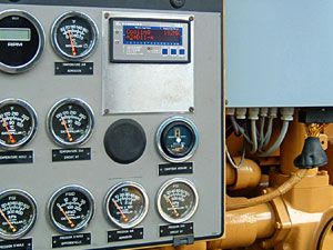
Tranducers Intelligent Sensors
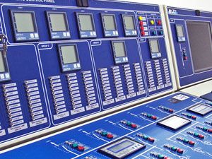
synchronizers

Solenoid Operated Gas Admission Valve

protective relays

Power Control Center
PMCC Technical specification: Rated Service Voltage: 415 V Rated Frequency: 50h Rated Insulation Voltage: 660 V Busbar System: TP-E or TPN-E (with isolable neutral) Max.Rating Of Busbars: 6000 A Fault Level Withstand: 50 ka / 65 ka FOR 1 SEC Degree Of Protection: ip 41/ 54 Proven interleaved busbar system for PCC / PMCC Concept: In conventional busbar system, conductors of each phase are grouped together. At higher current ratings in each phase, more than one flat of busbars placed quite close to each other are used. Skin effect & Proximity effect, causes uneven current distribution in each flat of the same phase which also results in unequal temperature rise in different phases. At higher currents increase in cross-sectional area of conductors does not yield proportionate increase in the current carrying capacity of the busbars. The interleaved busbar system offers a cost effective solution. Cable termination: Cable Termination is at the rear of the panel. Elecmech Standard PCC / PMCC panel dimensions are more than sufficient, However Panels can be custom designed for adequate space for termination of increased number aluminium cables for special cases such as for Material Handling Applications Stacker Reclaimer, etc. Though Bottom Cable Entry is Standard, TOP cable entries are possible, and in some non-standard cases with bottom busbar chamber Wide cable alley facilitates comfortable termination of a large number of cables. Shrouded link work for multi-tier configurations ensures complete safety in the cable alley. Standard panels are provided with captive screws / Quarter turn knobs. However customized Panels can be provided with Alphabetical Key lockable doors to prevent un-authorized access to the cable alley. Cabling Space (mm) Power Cables: 600 X 500 (depth 1200) 600 X 600 (depth 1300) 600 X 700 (depth 1400) Control Cables: Control Cables Terminals are provided vertically at the rear side panel on the left. So there is ample space for control cabling. Add on chamber: The cabling area can be extended further by providing an ADD ON CHAMBER to accommodate more cables if needed. Compartmentalised Design For ease of Maintenance and trouble free operation, Elecmech offers standard Single Tier ACB panels upto minimum 550 width, However Multitier designs are also offered for switchgear rooms with space limitations and for cost effectiveness. Standard Single Tier: for ACBs 630 to 6300A. Multi-Tier Arrangement: 2 tier arrangement for ACBs upto 1600A. PMCC: 8 feeders (fuse switches) in a panel. Flexibility in Compartment sizes. Compartment sizes can be 225 to 900 mm. Auxiliary Equipment Mounted by the side of ACB. Effective utilisation of space. Separate Chambers for Busbars, Droppers Auxiliary Busbars. Panels can be offered confirming to Form 2 / 3 / 4. Other PCC features The Power Control Centre (PCC) is a free standing and floor mounting type switchboard, suitable for indoor installation. To facilitate transportation, each PCC is split into shipping sections. Each shipping section is wrapped in an HDPE cover and packed in a wooden crate case. To arrive at the approximate overall dimensions of the packing cases, add 300 mm to the dimensions of the respective section. Each vertical panel is divided into distinct compartments Viz busbar chamber, Vertical droppers, Control busbar chamber, d/o feeders / fixed feeders, power cabling chamber at rear with control terminals. The compartments house main equipment like Air Circuit Breakers, Fuse Switches, Moulded Case Circuit Breakers and associated auxiliary equipment. Compartment doors are provided with Sprin Loaded Quarter Turn door fasteners, Which pressurises the door towards the panel frame, ensuring dust-proofness by the compression of gasket between door and panel frame. The cable alley doors are removable type. They are provided with Spring Loaded Quarter-turn locks or can be provided with door locks operable by a special key. Overall Dimensions Weight: 2475. Width : 550, 600, 700, 800, 900, 1000, 1100, 1200, 1300 mm. Depth : 1000 mm (base frame), 1200 mm, 1400mm 1600mm w/o front door. Depth : 1044 mm (base frame), 1244 mm,1444, 1644 with front door and rear door /cover. To increase cabling area, Add-on-chambers with a depth of 300 mm may be provided on rear. Add-on-chambers may also be used for bus duct entry. Relays are accommodated, usually below ACB compartment. usually it is of 450mm / 500 mm Height. Safety interlocks: All PCC feeders incorporate Safety interlock, Unless the ACB is racked out to isolated position, its compartment door cannot be opened. Conversely, the ACB cannot be operated unless the compartment door is closed. However, to facilitate maintenance and inspection, a defeat feature is provided for both these interlocks. Only QUALIFIED PERSONNEL are permitted to use the interlock defeat mechanism. Copper Busbars can also be provided on request. Aluminum Busbar used are of electrolytic E91E grade with manufacturer’s test certificate Busbars are punched using Multihole punching hydraulic press. The Multihole punch and die is specially deisgned for punching upto 4 Holes in one stroke with minimal burrs and no distortion of busbars. Punched Joints are then buffed smooth with special buffing tools to remove Aluminum oxide Layer. The Buffed aluminum busbar is then immediately coated with abrasive antioxidation paste. Excess paste squeezes out of the joints when the al bus joint is tightened removing aluminum oxide and also prevents the aluminum from being oxidized. Aluminum busbars are fastened using High Tensile Hardware High Tensile Fastners are tightened using adjustable and calibrated Torque wrench for optimum tightening torques. Thus optimum pressures are applied to Aluminum at fishplates and Joints ensuring minimal joint resistance and thus reducing heat loss and temperature rise. Non compromising Quality & Reliability Elecmech Panels are built to last for 20-25 year design life. Panels are Powder coated in our recently installed 11 Tank Hot process pretreatment powder coating plant which provides best possible degreasing derusting, phosphatising treatment for ms fabricated panels. Uniform powder coating quality is ensured by our stringent QC process. Standard interlocking schemes are available in our wide database for 2-Incomer, 1-Buscoupler and 3-Incomer with 2-buscouplers, also with standby generators. Standard protection schemes are available in our wide database for transformer incomers, outgoing feeeders with numerical relays from various manufacturers and also conventional relays. ERDA / CPRI Type Tested Panels with valid certification
...more
Motor Control Center
MCC Technical Specifications: Rated Service Voltage : 415 V Rated Frequency : 50 Hz Rated Insulation Voltage : 660 V Rated Current (maximum) : 4000 A Busbar Fault Level : 50 kA withstand (for 1 sec) 105 kA (Peak) Busbar System : TP-E or TPN-E Degree of Protection: IP 54 AS PER IS 2147 Fully Compartmentalised: Separate chambers for: Main Horizontal Busbars Droppers Control bus Feeder compartments Cables Versions: Single front Double front Overall Dimensions (mm): S.F / D.F Width 800 / 800 Height 2375, 2475 Depth 600 / 900 Maintenance Features: Elecmech D/o MCC Panels are designed to be maintenance free. Telescopic Rails & Racking Screw Positive guidance by Proven Rack and Screw arrangement Smooth movement of the module. Perfect alignment of contacts. No Banging of Busbars on insertion of modules. Eliminates the need to remove the module for routine checks / minor modifications. All identical drawout units are fully interchangeable thus minimizing downtime. Vertical T droppers minimizes the number of joints thus reducing heat losses and the number of joints to maintained. Tin-Copper Electroplated Aluminum T section Vertical Bus ensures that there is no direct Copper to Aluminum contact, ensuring no corrosion due to Cu to Al joint T Eletroplating of the T dropper elliminates additional Cop-al joint. Facility for Padlocking: Module in service and test position Power switches Drawout feeder door: Indicating lamps, push buttons, meters and selector switches are mounted on drawout feeder’s door. This door can be hinged out for inspection / maintenance of the connections. Only the d/o fdr door needs to be changed in case of change in specified control equipment. Design Features: Fully drawout module with 3 Service, Test & Isolated positions Service: Power & Control contacts engaged. Test: Control circuits can be tested. Power contacts disconnected. Isolated: Both power and control contacts disengaged. Access internal components without removing the module. Maintenance: Can be withdrawn for routine maintenance. Silver plated drawout Contacts: Drawout power contacts are of Silver plated copper. They offer high resistance to abrasion, lower mV drop, leading to lower wear and tear and longer life of the contacts Programmable Sliding Contacts: Depending on logic requirements, programmed sliding contacts are used to permit selective signals during service, test position or to operate in both service and test positions. Cable Alley: The MCC is provided with large cabling area. The cable chamber width is 250 mm internally. Aluminium cables can therefore be easily accommodated and terminated. Both top or bottom cable entry is possible. Gasket and Door lock: Standard panels are provided with captive screws / Quarter turn knobs. However customized Panels can be provided with Alphabetical Key lockable doors to prevent un-authorized access to the cable alley. The cable alley doors are removable type. They are provided with Spring Loaded Quarter-turn locks operable by a special key or with quarter turn knobs. Dimensions: Height: 2375. Width : 550+250=800 mm Depth : Single front: 600 mm (base frame), 622 mm with front door Depth: double front 900 mm (base frame), 944 mm with front and rear doors Module Design: Module size: Module size ranges from 1/8th to 1/2 in multiples of 75 mm. 225mm Module can accomodate: Switchfuse feeders & MCCB upto 63A 1/6th Modules accommodate DOL Starters upto 18.5 kW Spring Loaded position lock Variety of Feeders Larger Starters DOL / SD starter upto 160 kW are accommodated in a combination of feeders such as ½ (900 mm) for contactors and OL relays + 1/4th for SFU (450mm) Incomers can be Switch-fuse upto 800 A or ACB upto 1600 A Auxiliary Busbars: Upto 6 Sets control busses can be accommodated in the control bus chamber. Safety Features: Busbars and droppers are provided with heat shrunk PVC sleeving. The heat curing process ensures no voids or pinholes. Except at the Joints and Vertical dropper contact plates, the busbars are completely covered with insulating material. Sleeving also protects busbars against accidental contacts with hardware, tools and vermin. 'Click-fit' joint shrouds are provided to cover tap-offs and fish-plate joints. Thus there are very few possibilities of short circuit between phase and neutral or earth in the busbar chamber. The heat shrunk PVC Sleeving is provided in addition to the large clearances in the busbar zone. Merits: Secondary insulation protects against accidental contact with hardware, tools and vermin. Restricts the arc, in case of a fault, to the zone of initiation. Busbar Supports: Busbar supports are of SMC. This material has higher mechanical strength compared to conventional support material. Safety Shutters: Gravity operated safety shutters block access to the Vertical live T-droppers when the module is withdrawn from the service position. Scraping Earth System: Tinned Copper contacts on the fixed partition plate and d/o trolley ensures perfect earthing of d/o modules Safety: Operator safety is ensured by: Distinct vertical earth bar of full length for each panel front. Tinned Cu plated scraping earth contact on each drawout module of 'Make-first' and 'Break-last' type. All doors are individually earthed. Other MCC features ` Elecmech Motor Control Centre is a free-standing and floor mounting type switchboard available both in single front and double front versions, suitable for indoor installation. To facilitate transportation, the MCC is split into multiple sections. Each section is wrapped in an HDPE cover and packed in a wooden crate case. To arrive at the approximate overall dimensions of the packing cases, add 300mm to the dimensions of the packing cases, add 300mm to the dimensions of the respective section. Each vertical panel is divided into distinct zones for busbars, feeders, power cabling and control busbars. Horizontal busbars (HBB) are located at the top of the panels. The phase sequence, from rear to front, is N-R-Y-B. Where the number of bars per phase exceeds two, the HBB is split into two packets per phase. The phase sequence is N-R1-Y1-B1-R2-Y2-B2 from rear to front. The droppers are located behind the module chamber and isolated from the unit compartment with an insulating barrier. The phase sequence, as seen from front left to right, is R-Y-B-N. Click-fit Busbar joint shrouds can be provided on the HBB for complete insulation. Shrouds can be easily removed for tightening the joints. Control bus, are located in the top-front chamber of the panel. In the double front MCCs, auxiliary busbars are placed in one of the fronts, and tap-offs are taken for feeders in both the fronts. The incoming power contacts are located on the right hand side, while the outgoing power contacts are located on the right hand side rear. The starter unit in the fully drawout version has the following positions: Connected (service) position Test position Disconnected (isolated) position The connected/test/disconnected positions are indicated by matching red lines on the bottom tray of the compartment and the red arrow mounted on the withdrawable unit. The control contacts, i.e. the Secondary Isolating Contacts (SICs) are mounted in 2 columns on the drawout module. The rear column comprises SIC making in “Service” position. The front column can have the following varieties of SICs: Service + Test Test only Service only For 225 and 300mm units, SICs can be located on LHS also. Such control terminals are duplicated in the cable alley. Wiring from the LHS SICs to the fixed terminals is factory-assembled and routed through a PVC duct mounted on the bottom side of upper tray for respective unit For 450 to 900 mm units. SIC are located on the right hand side only.
...more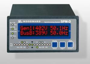
Marine Shore Supply Control

Marine Energy Systems Protection Relay

Load Controls Demand Side Management

Grid-connected Power Inverters
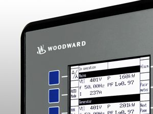
Genset Controls

gateways

Feeder Management Controls
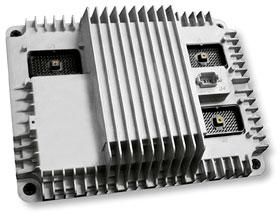
Electronic Diesel Injection System

electrical actuators

Steam Turbines Digital Control Relay
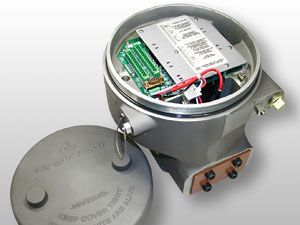
Current to Pressure Converters

Automatic Voltage Regulators
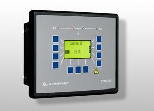
Automatic Transfer Switch Controls
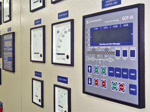
Automatic Mains Failure Controls

Electrical Bus Duct
Be first to Rate
Rate This