
Water, or Liquid, in bladder type Surge Tank
The air charge is contained within the tank, whilst the liquid from the main flows into and out of the bladder. Like the air in bladder design, the liquid does not come into contact with the tank walls nor the air charge, so again, the air charge cannot be absorbed by the pumped liquid and so air losses due to absorption are minimal. The pumped liquid from the main flows into and out of the bladder and will not come into contact with the tank walls, again compatible materials must be selected. As for the air in bladder design, the bladder is often made from a highly elastic rubber, such as butyl rubber, and may be sized to expand to fit the entire vessel. For this design the whole tank is pre-charged at installation with a pre-determined pressure to give the correct operating level in the tank when the unit is connected to the main and at the operating pressure. Again, there must be an anti extrusion plate fixed at the outlet from the vessel to prevent the bladder from being drawn into the main at low pressures and like the air in bladder design, the anti-extrusion plate and inlet size must be selected so that they do not impose a restriction on the flow into and out of the vessel. Each bladder vessel comes with these standard features: Safety relief valve Pressure gauge Air fill valve Drain connection Internal membrane (bladder) Any of our standard bladder vessels may be fitted with the following optional features: Leak detection system Level gauge Level transmitter Pressure transmitter Drain valve Flo-Dyne bladder vessels are pressure vessels and as standard may be manufactured in ordinary carbon steel, low temperature carbon steel or 304/316 stainless steel to the requirements of the pressure vessel code of your choice. Typically this will be ASME VIII or PD5500, however we can also manufacture to IBR or your local requirement. We will CE mark the equipment if it is to be used within the European Union, if the equipment is to be used elsewhere we will apply a CE mark where requested if possible.
...more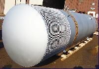
vent silencers
Vapour Dome Suction Dampener
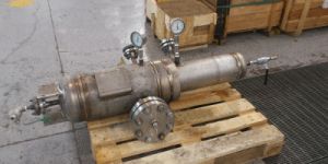
Reciprocating pumps often suffer from pulsation problems on both the suction and discharge side. Many of the problems can be traced to poor suction conditions where the pressure at the inlet to the pump is less than that required by the pump manufacturer. The suction pressure available at the inlet to the pump is often referred to as either NPSHa (Nett Positive Suction Head available) or NPIP (Nett Positive Inlet Pressure). Fitment of a Flo-Dyne Vapour Dome Suction Stabiliser at the pump suction will eliminate all NPSH problems and ensure a smooth running pump. For maximum effect the suction stabiliser may be combined with the Flo-Dyne liquid filled discharge pulsation dampener. It is ideal for use on liquids which readily absorb gas charges, or where membranes and cellular foams are not suitable. The Flo-Dyne Vapour Dome Suction Stabiliser works in exactly the same way as our standard Suction Stabiliser, in that we provide a gas cushion at the top of the equipment by locally heating the liquid until it vapourises. In this way the pulsation dampener works by exploiting three basic properties which each contribute to eliminate pulsation and NPSH problems: Dampening Effect: Every suction stabiliser has a gas charge which, as it is obviously more compressible than the liquid being pumped, will provide a capacitance or spring effect which in turn will absorb the pulsation created by the abrupt flow change as the pump suction valves open and close. Separation Effect: Flow through the suction stabiliser is slowed and rotated before leaving through the exit nozzle. By controlling the transit time and flow velocities through the equipment, entrained gases are encouraged to break out of solution and collect at the top of the stabiliser instead of passing directly into the pump inlet nozzle which reduces the quantity of entrained gas entering the pump, thereby reducing or eliminating the conditions for cavitation to happen. Volume Effect: The suction stabiliser acts as a mini-storage tank, the stabiliser provides a full charge of liquid when the pump valves open and allows for smooth acceleration and deceleration of the liquid in the line. By providing the tank volume close to the pump, acceleration head is eliminated and the possibility of cavitation occurring in the pump cylinders is eliminated. The suction stabiliser will provide complete compliance with the requirements of API674 for pulsation levels. All units are constructed to meet your local and national regulatory requirements and will be made either as piping, or pressure vessels, to fit into your piping. All units are constructed to meet your local and national regulatory requirements and will be made either as piping, or pressure vessels, to fit into your piping. Units are typically built to ASME VIII vessel code, or ASME B31 piping code, however, supply to other national codes such as IBR, CODAP, and Stoomwezen is always possible. Each unit may be supplied with connecting flanges, or with bevelled connections, and ready for welding directly into your pipework system. A sight gauge, suitable level instrumentation, or an automated control system can be provided to monitor or control the gas / liquid level.
...more
Suction Stabiliser
Reciprocating pumps often suffer from pulsation problems on both the suction and discharge side. Many of the problems can be traced to poor suction conditions where the pressure at the inlet to the pump is less than that required by the pump manufacturer. The suction pressure available at the inlet to the pump is often referred to as either NPSHa (Nett Positive Suction Head available) or NPIP (Nett Positive Inlet Pressure). The Flo-Dyne Suction Stabiliser is a gas, or vapour, charged pulsation dampener which if installed at the pump suction will eliminate all NPSH problems and ensure a smooth running pump. For maximum effect the suction stabiliser may be combined with the Flo-Dyne liquid filled discharge pulsation dampener. It is ideal for use on pumping systems where pumping conditions change, or where the pumped liquid is not compatible with rubber membranes or cellular foams. The Flo-Dyne suction stabiliser works by using a gas cushion over the pumped liquid so that we can then reduce acceleration head and pulsation by exploiting three basic properties, which each contributes to the overall elimination of pulsation and NPSH problems: Dampening Effect: Every suction stabiliser has a gas charge which, as it is obviously more compressible than the liquid being pumped, will provide a capacitance or spring effect which in turn will absorb the pulsation created by the abrupt flow change as the pump suction valves open and close. Separation Effect: Flow through the suction stabiliser is slowed and rotated before leaving through the exit nozzle. By controlling the transit time and flow velocities through the equipment, entrained gases are encouraged to break out of solution and collect at the top of the stabiliser instead of passing directly into the pump inlet nozzle which reduces the quantity of entrained gas entering the pump, thereby reducing or eliminating the conditions for cavitation to happen. Volume Effect: The suction stabiliser acts as a mini-storage tank, the stabiliser provides a full charge of liquid when the pump valves open and allows for smooth acceleration and deceleration of the liquid in the line. By providing the tank volume close to the pump, acceleration head is eliminated and the possibility of cavitation occurring in the pump cylinders is eliminated. The suction stabiliser will provide complete compliance with the requirements of API674 for pulsation levels. All units are constructed to meet your local and national regulatory requirements and will be made either as piping, or pressure vessels, to fit into your piping. Units are typically built to ASME VIII vessel code, or ASME B31 piping code, however, supply to other national codes such as IBR, CODAP, and Stoomwezen is always possible. Each unit may be supplied with connecting flanges, or with bevelled connections, and ready for welding directly into your pipework system. A sight gauge, suitable level instrumentation, or an automated control system can be provided to monitor or control the gas / liquid level.
...more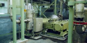
Suction Dampeners for reciprocating pump
Suction Dampeners for reciprocating pump suction lines to eliminate pressure pulsation and acceleration head
...more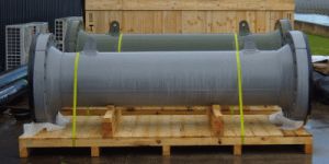
Steam Ejector Suction (LP) Silencer
The Roots type blower is a positive displacement lobe pump which operates by pumping, or moving, a fluid, usually air, but in some cases a process gas, using a pair of inter-meshing lobed rotors, which have a profile that looks not unlike the number 8. When operating, the fluid is trapped in the outer pockets surrounding the lobes and is carried, or progressed, from one side of the machine to the other. The lobe shaped rotors (usually two lobes, but it can be 3 or 4) work in tandem and move the fluid, usually air, from one side of the machine to the other. The lobes do not grab, or scoop the air out of the inlet pipe, but rather as they pass the inlet opening they cause a local low pressure area inside inlet port of the machine into which the fluid will then flow. As the rotors continue to turn the fluid that has entered the machine is trapped by the rotors and progressed from the inlet side to the outlet side. On reaching the outlet side the fluid has no choice but to be pushed out into the discharge pipe. Each time one of the rotor tips passes either the intake or exhaust port, the passing of that tip causes a pressure pulse to be generated. Therefore in the case of a blower with rotors that have 2 lobes there will be 4 pulses for each complete revolution of the pair of rotors (2 pulses from each rotor for each revolution). This allows for a relatively easy estimation of the principal frequency of pulsation that the machine will generate.
...more
Steam and Gas Vent Silencer
Steam and Gas Vent Silencers for venting process gases, HP and LP steam, blast furnace gases and other gases or vapours from pressure.
...more
Steam and Gas Ejector Silencer
Suction and Discharge silencers for Surface Jet Pumps where low pressure drop and noise reduction performance are critical. Units are normally built into pressure piping that forms part of the overall skid.
...more
Roots Blower Inlet silencers and Pulsation Dampener
The Roots type blower is a positive displacement lobe pump which operates by pumping, or moving, a fluid, usually air, but in some cases a process gas, using a pair of inter-meshing lobed rotors, which have a profile that looks not unlike the number 8. When operating, the fluid is trapped in the outer pockets surrounding the lobes and is carried, or progressed, from one side of the machine to the other. The lobe shaped rotors (usually two lobes, but it can be 3 or 4) work in tandem and move the fluid, usually air, from one side of the machine to the other. The lobes do not grab, or scoop the air out of the inlet pipe, but rather as they pass the inlet opening they cause a local low pressure area inside inlet port of the machine into which the fluid will then flow. As the rotors continue to turn the fluid that has entered the machine is trapped by the rotors and progressed from the inlet side to the outlet side. On reaching the outlet side the fluid has no choice but to be pushed out into the discharge pipe. Each time one of the rotor tips passes either the intake or exhaust port, the passing of that tip causes a pressure pulse to be generated. Therefore in the case of a blower with rotors that have 2 lobes there will be 4 pulses for each complete revolution of the pair of rotors (2 pulses from each rotor for each revolution). This allows for a relatively easy estimation of the principal frequency of pulsation that the machine will generate. Whilst the frequency of the noise from the passing of the rotor tips at the intake and exhaust ports is well understood, there is a second noise mechanism where the fluid tries to pass back through the machine from the high pressure side to the low pressure side by "slipping" around the rotors at their tips. This is an aerodynamic noise mechanism and is less easy to predict as the noise level changes with the speed of the blower and the gap between not only the rotors, but also between the gap between the rotors and the casing. The noise generated by these two mechanisms are quite different. The sound from the passing of the rotor past the open inlet port will have a certain frequency, or tone, which on large low speed machines can literally sound like a large helicopter, whilst on smaller machines which operate at higher speeds this tone may sound like a tuning fork. The aerodynamic sound from the slippage of the fluid back past the rotors is not usually obviously tonal in nature, but rather has a more broadband nature to it, not unlike a valve or pipe exhausting to atmosphere at high velocity.
...more
Roots Blower Discharge Silencers and Pulsation Dampener
The Roots type blower is a positive displacement lobe pump which operates by pumping, or moving, a fluid, usually air, but in some cases a process gas, using a pair of inter-meshing lobed rotors, which have a profile that looks not unlike the number 8. When operating, the fluid is trapped in the outer pockets surrounding the lobes and is carried, or progressed, from one side of the machine to the other. The lobe shaped rotors (usually two lobes, but it can be 3 or 4) work in tandem and move the fluid, usually air, from one side of the machine to the other. The lobes do not grab, or scoop the air out of the inlet pipe, but rather as they pass the inlet opening they cause a local low pressure area inside inlet port of the machine into which the fluid will then flow. As the rotors continue to turn the fluid that has entered the machine is trapped by the rotors and progressed from the inlet side to the outlet side. On reaching the outlet side the fluid has no choice but to be pushed out into the discharge pipe. Each time one of the rotor tips passes either the intake or exhaust port, the passing of that tip causes a pressure pulse to be generated. Therefore in the case of a blower with rotors that have 2 lobes there will be 4 pulses for each complete revolution of the pair of rotors (2 pulses from each rotor for each revolution). This allows for a relatively easy estimation of the principal frequency of pulsation that the machine will generate. Whilst the frequency of the noise from the passing of the rotor tips at the intake and exhaust ports is well understood, there is a second noise mechanism where the fluid tries to pass back through the machine from the high pressure side to the low pressure side by "slipping" around the rotors at their tips. This is an aerodynamic noise mechanism and is less easy to predict as the noise level changes with the speed of the blower and the gap between not only the rotors, but also between the gap between the rotors and the casing.
...more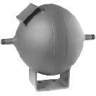
Pulsation Dampener

Noise Measurement
Noise Measurement services to identify noise problems, provide written reports of levels and compliance with standards.
...more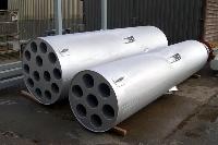
Industrial Silencers

Inline Silencers
In-Line silencers for compressors, control valve, pressure reducing valves, gas compressors and surface jet pumps, whether built into, or as part of your piping, or as standalone equipment.
...more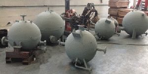
Flo-Dyne Standard Discharge Pulsation Dampener
Pulsation dampeners are often necessary for multi-plunger high pressure reciprocating pumps which produce damaging levels of pulsation and vibration. These forces can be significantly reduced by the Flo-Dyne non-charged maintenance-free pulsation dampener which is completely filled with the pumped liquid. Our unique spherical in-line design results in optimized low weight and cost and is ideal where rubber bladder or metallic diaphragm types cannot be applied. Should you require, for our standard dampeners, we can model your system, analyse the pulsation levels and simulate the mechanical response, with the same detail and rigour as needed by API674. In many cases we can show you that a smooth running system can be achieved with dampeners that are smaller, lighter, and so cheaper, than that required by API674. Volume The volume is selected by Flo-Dyne to provide sufficient bulk so that when each plunger discharges its slug of liquid the compressibility of the liquid will absorb a proportion of the pulsation energy. The volume of the dampener must be chosen to be massive compared to the slug of liquid discharged by each plunger on each stroke, and not too large as to be uneconomical for manufacture. Where required we can offer discharge pulsation dampeners that work upon this feature of compressibility of the volume alone, however such dampeners tend to be both massive and expensive.
...more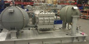
Discharge Pulsation Dampeners For Reciprocating Pump
Maintenance Free Liquid Filled Discharge Dampeners to provide smooth running systems and compliance with API674
...more
Discharge Dampeners for reciprocating pump
API674 pump discharge pulsation dampeners are often a necessary accessory for multi-plunger high pressure reciprocating pumps, as such pumps can produce damaging levels of pulsation and vibration as each slug of liquid is discharged from the cylinder out through the discharge valve and into the pipework. As the slug of liquid exits the pump cylinder it is will be pushed into a pipeline that is already full of liquid. If the liquid volume in the pipe cannot be fully compressed to make space for this new slug of liquid, or if the pipe containing the liquid will not stretch to give some additional volume, then the pressure in the liquid will rise and a pressure pulse will occur. How high this pressure pulse goes will depend on how fast the slug of liquid is pushed out it into the pipeline, the compressibility of the liquid already in the pipeline and the stiffness of the pipe material. The magnitude of the pressure pulses that are generated at the pump, and the forces that they impose on the piping system can be assessed using the guidance given in API674. This specification, produced by the American Petroleum Institute provides conservative guidance that enables the use of simulation analysis to design out these pulsation forces either through modification of the piping system, or by the installation of a pulsation dampener in the discharge pipework, usually positioned immediately downstream of the pump. This discharge dampener may take one of several forms, however, whichever form is fitted they all have the same thing in common in that they introduce a calculated amount of elasticity into the piping system that will expand and/or contract as each new slug of liquid leaves the pump and enters the piping system, thereby allowing the system to accept each new slug of liquid with minimal pressure rise. Our liquid filled discharge dampeners offer full compliance with API674 by utilising the compressibility of the liquid volume, and the pressure drop across the equipment. We can demonstrate compliance with API674 through our full API674 analysis service that simulates the sizing and effectiveness of the solution according to the most rigorous design approach. Design and manufacture of the equipment will be fully in accordance with your specifications, such that the dampeners become part of the pipeline, and are simply forgotten. They are a true fit and forget item. With hundreds of units supplied, and over 30 years of experience in supply, our equipment has a proven track record of reliability and performance. Carbon steel construction is standard, but other materials such as 304/316 stainless steel, duplex or super duplex steels are available for pressures ranging from as little as 50 BarG and upwards to match the rating of your piping. If you can design the piping can take the pressure, then we can build a dampener that will fit right in. Whether this just requires some straight forward pressure vessel calculations, or fully detailed Finite Element Analysis (FEA), to prove the design, our in-house engineers have the tools needed to prove the design. Units can be built to all British, European, American and Indian pressure vessel codes, with CE marking will be applied to equipment that is destined for the European Union. A few of the fluids that we have built equipment to handle are; Water, Ammonia, Carbamate, Hot oils, Bitumens, CO2, MEG, TEG, plus various hydrocarbons
...more
Diffuser Silencer
Simple diffuser silencers to provide an economic and reliable noise reduction when full size absorptive silencers are either not necessary, or not possible.
...more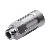
Control Valve Silencers

Compressor Suction Silencer
High pressure compressor silencers and inline compressors silencers are often specified for axial, centrifugal and turbo compressors which create broad spectrum noise with peaks at the blade passing frequencies. If this noise is left untreated it will propagate into the attached piping where it will be radiated into the surrounding area. In some cases this will be a hazard to nearby workers, whilst in other cases it will become an annoyance to local residents. In addition many piping systems suffer from propagation of low frequency noise both within the gas stream and along the pipewall. Low frequency noise is often difficult to treat, in cases where this noise is travelling in the gas stream the silencer must be properly designed to attenuate such low frequencies, or the noise will simply pass straight through the silencer unaffected. In addition, in many cases the acoustic performance of the silencer can be compromised by noise travelling along the pipe-wall. This is known as "flanking noise" and if left untreated will simply travel along the casing of the silencer unimpeded rendering the silencer ineffective. The custom designed Flo-Dyne compressor inline silencer will treat these special noise problems to give a highly effective silencing solution.
...more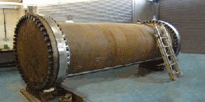
Compressor Discharge Silencer
High pressure compressor silencers and inline compressors silencers are often specified for axial, centrifugal and turbo compressors which create broad spectrum noise with peaks at the blade passing frequencies. If this noise is left untreated it will propagate into the attached piping where it will be radiated into the surrounding area. In some cases this will be a hazard to nearby workers, whilst in other cases it will become an annoyance to local residents. In addition many piping systems suffer from propagation of low frequency noise both within the gas stream and along the pipewall. Low frequency noise is often difficult to treat, in cases where this noise is travelling in the gas stream the silencer must be properly designed to attenuate such low frequencies, or the noise will simply pass straight through the silencer unaffected. In addition, in many cases the acoustic performance of the silencer can be compromised by noise travelling along the pipe-wall. This is known as "flanking noise" and if left untreated will simply travel along the casing of the silencer unimpeded rendering the silencer ineffective. The custom designed Flo-Dyne compressor inline silencer will treat these special noise problems to give a highly effective silencing solution. Optimum design of a compressor silencer requires not just an engineering solution to the acoustic baffle as well as the containing shell. Failure to provided the correct balance of; Fibre diameter, bulk density and composition Perforated plate hole diameter spacing and thickness Flow passage width and length Packing depth and packing protection Will result in poor acoustic performance and high pressure drops. Flo-Dyne engineers will custom design the entire acoustic baffle and the containing shell providing an optimum total silencing solution thereby ensuring that the silencer is at its most effective during operation. This will include examining the higher frequencies associated with blade passing and the lower, longer wavelengths associated with pipe-wall resonances and flexing.
...more
Blower and Fan Silencer
Inlet and outlet silencers for rotary, roots type, blowers, screw compressors and centrifugal fans. Units are designed to eliminate the tonal noise produced by these types of equipment.
...more
Air in Bladder Surge Tank
Bladder tanks are usually supplied in one of two configurations and are used to reduce pressure surges in pipelines. The air charge is contained within the bladder inside the tank. The air charge does not come into contact with the liquid in the tank and so cannot be absorbed. Air charge losses due to absorption are therefore not possibel as they have been eliminated. The pumped liquid from the main flows into and out of the main tank, it will come into contact with the tank walls and so compatible materials must be selected. The bladder is often made from a highly elastic rubber, such as butyl rubber, and may be sized to expand to fit the entire vessel. The bladder will typically be pre-charged at installation with a pre-determined pressure to give the correct operating level in the tank when the unit is connected to the main and at the operating pressure. There must be an anti extrusion plate fixed at the outlet from the vessel to prevent the bladder from being drawn into the main at low pressures. The anti-extrusion plate and inlet size must be selected so that they do not impose a restriction on the flow into and out of the vessel, otherwise the unit will not function correctly as a surge tank. Each bladder vessel comes with these standard features: Safety relief valve Pressure gauge Air fill valve Anti-extrusion plate Drain connection Internal bladder (membrane)
...more
Acoustic filter
Tuned acoustic filters to attenuate tonal noise from reciprocating and multi-lobe pumps and compressors
...moreBe first to Rate
Rate This