
Heater Plate
Heater plate is equipped with uniquely designed & heavy duty heaters with PID temperature controllers with 3-phase solid state relays mounted in easily replaceable PC boards. USING THE HEATER PLATE The Heater plate of Hot Foil Attachment is manufactured from a specially developed graded casting and machined upto a highest accuracy. It has tapped (M6) holes over it's surface. The thickness of the heater plate is 17.5 mm. So it is possible to use a stamping dye of the image height 6.5 mm (max) on the heater plate. If one desires to use a thin dye (image height of 1.5 mm approximately), it is required to paste the same thin dye on an aluminium plate of 4 to 5 mm thickness. Some strong rubber solution or any other adhesive. A full size aluminium plate may also be permanently fixed on the heater plate. HOLDING & MOVING THE DYE To hold and move the dye for getting proper registration, different clamps are provided. To use calmp no.1, which gives much firm hold, it is essential to reduce the dye thickness at the borders by around 2.5 mm. Clamp no.2 gives a lesser firm hold on the dye but it is more easy to use. It does not require any reworking of the dye. Movement of the dye is quite easy and a very minute adjustment is also possible with these clamps. PRECAUTIONS The operator has to be very cautious while fixing the dye on the heater plate. While mounting the clamps, never use invalid screws of longer length. This will damage the heater element placed inside the heater plate. It may also lead to a serious short circuit and the unit may get damaged. Never leave any screws loose. Use only the holes provided by the manufacturers. Creating additional holes for covering more printable area is risky. It may lead to serious accidents and damage to the machine. USEFUL TIPS A 100% firm contact between the surface of the heater plate and bottom of the stamping dye (or the aluminium plate beneath it) is extremely essential. Any gap may result to non-conduction of the heat. Selection of proper foil, make-ready material and make-ready technique and properly mounted dye of the best quality are the proven keys of getting good stamping results. Excessive temperature and pressure would never help to produce better results. One has to develop his own make-ready methods and choice of material for achieving more and more improvement.
...more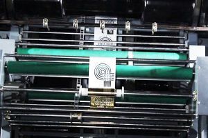
Foil Pulling Unit
Foil pulling station allows better accuracy. All attachments are laced with foil saving features and user-friendly operating systems with self fault diagnostics.
...more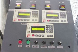
Electronic Control Panel
This is the real Control Part of the attachment. It comprises of two major divisions; a.) Motor Controller - it has a CPU, a Stepper Drive, a Power Supply and a user friendly keyboard with display. b.) Temperature Controller - this controls the temperature of the heater plate. It has as PID type temperature controller and a 3 phase solid state relay card to drive the power of the heater plate. High Voltage Power Supply- This part is located in the left most slot of the mother board. It has a Red colored LED (light) on this. The light glows when the power is , switched ON. Output voltage of this card is 55 volts and 70 volts D.C. Low Voltage Power Supply- This is inserted in the 2nd slot of the mother board. It has a green colored LED on it. Output voltages of this part are -5v, 15 v,5v D.C. CPU- This card contains the micro controller, which is responsibie for the total, control. It has a gray colored flat cable, 'which goes to the keyboard and display. Location of this part is third slot on the motherboard. Stepper Drive- This part supplies power to the stepper motor. Its location is fourth slot of the motherboard. Failure of this card results in power failure of the motor. Temperature Controller- This device is Em advanced temp. Controlier with PID control technique. It controls the temperature of the heater plate. Solid State Contactor- It is mounted on an insertable card. Its location is in the fifth slot of the motherboard. Keyboard & Display- This is mounted on the front plate of the control panel. It is used to feed and see the variables of the foil pulling. MCB- It is located on the left wall of the control panel. It is used to disconnect the three phase power of trreheater plate. Motherboard- This holds all the electronic cards and connects them to each other as well as the external devices. Connectors
...moreBe first to Rate
Rate ThisOpening Hours
Share your Correspondence Details to receive messages from PRECISE EQUIPMENTS PVT. LTD