thruster drum brakes
Thruster brake is a device used to retard the speed of moving machinery and to stop it accurately to the desired position. The braking force is applied to the brake shoes by a pre-stressed comprising spring. The shoes press on the rotating brake drum retarding its speed and finally stop it. The releasing of the brake drum and compressing of the spring is done by thruster.
...more
S.S. Punch Grid Resistance Box
Introduction ROLEX make resistance boxes are designed to meet requirements of A.C & D.C. application for E.O.T. Cranes, Winches, Rubber Mills, Flour Mills, Coal Mines, Cement Mills, Power Plants, Conveyors, Coke Oven, Blowers etc. for Speed control and developing Starting Torque. Assembly and Function Rolex punched Steel resistance boxes Consist of Grids Punched from Nickel Chromium Steel Alloy Sheet. These grids are shock and vibration proof. These resistors are specially suited for Steel mill duty. Coal mines etc. These resistors are available in a wide range of Current ratings from 7 Amps to 800 Amps continuous. The series connection between adjacent grids is by means of copper jumpers. The resistors, after overloads of moderate duration become red hot but no damage is caused and retains their shape after overload disappears. Features: Economical Less Weight Spares Easily Available Easy For Maintenance Special Anti-vibration method adopted
Material : G.I. Sheet
...more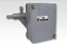
rotary limit switches
Rotary geared limit switch is used to trip motor supply when the moving loads reach the extreme end positions of working zone. Rotary geared limit switches are suitable for use on reversing drives such as Hoists, winches, rolling mills and various other mechanisms used in steel plants such as coke oven, feeding machinery etc.
...more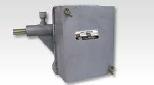
Rotary Geared Limit Switch
1,800 Per Piece
Voltage : 500 V

Master Controller
Introduction Master controllers are used for operation of contractor’s equipment controlling E.O.T. Cranes & Rolling mills drives. The controllers are made in dust proof enclosure in IP-54 degree of protection, up to 6 notches either side with maximum 24 contacts as per desired sequence with spring return arrangement & deadman's handle arrangement are available. Master Controllers are compact up to 4-0-4 step suitable for Grab-Hoist, CT-LT maximum contacts 16 per motion with spring return arrangement. Assembly and Function Master controllers are of cam type where in contacts are actuated by individual cams mounted on operated shaft. Master controller is housed in enclosure and provided with an easily removable cover with ample area for maintenance. The cam shaft is mounted on bearing bushes on walls of housing. The cams are made of derlin material and fixed on square. Deadman's control : This consists of one auxillary contact of two circuit block (1 NO+ 1 NC) operated through a spring loaded push button provided on joystick handle in case of operator looses the grip over button during operation, motion will come to stop as main contactor will be de-energised. Spring Return arrangement : The master / cam controller can be provided with spring return arrangement whereby handle returns to the neutral position when it is released. Features: Wide electrical clearance Long life Simple in operation Easy in installation
Material : M.S sheet
Voltage : 500 V
...more
Magnetic Clutch
Introduction Clutch is used to transmit the power only & Brake is used to stop machine only. When starting & stopping both are to be controlled, Clutch and Brake both are to be controlled; Clutch and Brake both are required. Clutch will engage drive to machine and when brake is applied clutch will only disconnect drive from machine and brake will stop machine only. The drive will keep rotating. This is ideal for inching operation. These are in two parts: 1) Magnet Body & 2) Armature Plate. These Clutches / Brakes engage when current is supplied to them. Slip rings are fitted to clutch only. The liner wear can be adjusted and wearing parts are replaceable. A sprocket, gear or pulley can be mounted if desired.
...more
Geared Coupling
Introduction Geared couplings are used to connect two different shafts or offset shafts. Geared couplings are made of EN material to absorb shocks. Geared coupling consists of gear which transmit the motion smoothly by absorbing shocks.
...more
electro magnetic brakes
Introduction For infallible operation of machinery, modern methods are necessary, any machine which requires its motion to be controlled, whether it is a lifting Crane, Hoist, Winch or Mining Haulage today employs an Electro Magnetic Brake, enabling the operator not only to control the motion but also to hold the load at any desired point without danger of falling, merely by release of the starting handle. Electro magnetic Brake is adequate equipment for safer operations of machinery. Electro magnetic Brakes are used when a load must be stopped rapidly to prevent it from rotating. Electro Magnetic Brakes find its use in Paper Mills, Drives of certain textile machines, Sugar Mill Machinery, Rubber Mixing Mills. .. Assembly and Function The Shoes are of cast iron and other components are of fabricated steel. The lever is hinged on the main arm, which is connected to the side arm through a tie rod, and is stressed by a pre-loaded compression spring. The compression of the spring can be adjusted to set the braking torque to desired value. The brake liner of selected quality material is riveted to the shoes by aluminum rivets. A.C. solenoid with laminated magnetic sheet steel houses a copper magnetizing coil which is impregnated with Class F materials. The plunger which is connected to the lever, is drawn in to the coil, when it is energized with AC source. This loads the spring and releases the brake shoes from the brake drum. When the supply is cut off, the plunger is pulled out of the coil, and spring force clamps the brake shoes on the brake drum and the brake is applied.
...more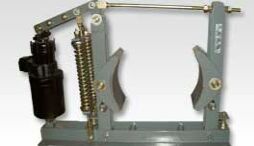
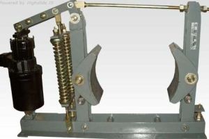
Electro Hydraulic Thrustor
Thruster brake is a device used to retard the speed of moving machinery and to stop it accurately to the desired position. The braking force is applied to the brake shoes by a pre-stressed comprising spring. The shoes press on the rotating brake drum retarding its speed and finally stop it. The releasing of the brake drum and compressing of the spring is done by thruster.
...more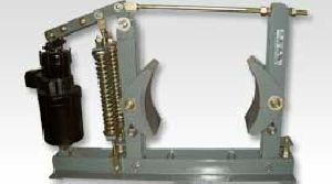
Electro Hydraulic Thruster Brakes
Introduction Thruster brake is a device used to retard the speed of moving machinery and to stop it accurately to the desired position. The braking force is applied to the brake shoes by a pre-stressed comprising spring. The shoes press on the rotating brake drum retarding its speed and finally stop it. The releasing of the brake drum and compressing of the spring is done by thruster. Assembly and Function A thruster shoe brake has a pair of cast iron shoes which are lined up with friction pads. The shoes are hinged on main arm and side arm of the brake, each of them have a hinge pin fitted in the base. They are connected to each other on top by a tie rod, which is hinged in the main arm and locked to the swivel block in the side arm, by a lock nut. A crank lever is hinged on the main arm and the other end is fixed to the top clevis of the thruster by a hinge pin. A brake spring is fixed on the main arm and is pre-loaded by a locknut on the lever. The pre-tension in this spring decides the braking torque. The thruster is fitted on the base by a hinge pin. When the thruster is not energized, the brake shoes are pressed on the brake drum fitted on the drive motor shaft and hold it under the effect of braking force provided by the spring. In such condition, the brake is applied and the drum cannot rotate. As the piston travels upwards the angle lever turns, pushes the brake rod and compresses the brake spring. Simultaneously, the brake lever on the other side of the wheel (Brake Drum) is retracted. When the first lever reaches the stop on the brake base member the brake lever at the thruster begins to move, releasing the brake drum. Features: Rugged design Consistent braking performance Robust in construction Long life Trouble free maintenance Easy in service
...more
Electro Hydraulic Thruster
Introduction In addition to wide range of applications in mechanical engineering applications, the thruster operated drum brakes are mainly used in material lifting and handling equipment, mainly because their 'Fial-to-safety' designs ensure safety to men and machines in the event of over failure. With the advancement in electricl drives and electronics, the drives have pushed the mechanical systems to high level of operations and demanding safer and reliable braking loads moving at much higher speeds than earlier. Continuous developments in product improvisation and assured quality checks, the thrusters offer compact, reliable yet economical solutions to most of the industrial applications.. Assembly and Function The two main sub-assemblies of the hydraulic thruster, the electric motor and the hydraulic unit are co-axially assembled form the working unit. In the switched off state (de-energised) the piston is at its lowest position due to external load (as brake spring of the drum brake), and the brake is applied. When energized, the electric motor drives the pump and delivers working fluid under the piston axially in the guided path, and delivers thrust or force required to operate the attached devise (like thruster brake) via the piston rod and the eye-lug attached to it. The working stroke can be steplessly controlled by external load. The thruster is designed for long trouble free service. The motor windings are designed to meet contingencies. The bearings are adequately sized. Features: Gentle Application and release of brake without jerks and shocks Compact unit Constant magnitude Self aligned movement Low power consumption Minimum maintainance Easy mounting and dismounting
...more
Disc Brake
Introduction Very compact and modern in design. Foundation is not necessary as they are directly mounted on non-driving end shaft of the motor. It consist of Liner Plates (Brake Disc) with square hole ate the centre. One corresponding piece of square hub is supplied with the Brake. This hub is keyed to the motor shaft and the Liner Plate is free on this hub. Normally Liner Plate is gripped between two discs with the help of Spring Pressure. They work on 230 / 415 V.A.C. When the current is supplied to the brake one disc is attracted by electromagnet against spring pressure and Liner Plate is released. Thus the Brake is 'off'. Once the Brake is set it does not require adjustment or maintenance. When the liner plate wears with the use then only air gap is required to be maintained periodically. An arrangement to release the brake manually could be provided on request
...more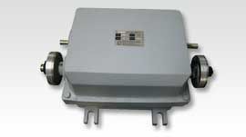
Differential Grab Limit Switch
Introduction (MODEL NO.RI-1121):A Grab Differential limit Switch is Driven by holding and closing winches used in Auxiliary circuit for single lever grabs control. It is used to stop or start the function of the motor at required preset position, irrespective of the height of the grab. It works at the highest & lowest grab position. A key is provided with the switch to release the locking nut to Adjust the cam disc.
...more
crane control equipments
Lever Limit Switches are used for Heavy duty E.O.T. Cranes, Hoists to prevent over travel of hoisting motion on power and control circuit up to 500 V and 40 Amps. continuous current. The limit switch normally remains closed and cuts off power to stop the motor of the crane. The Lever limit switch operates when it reaches a predetermined position when the lever is moved over a projecting member fixed on the girder.
...more
Counter Weight Limit Switch
Introduction Counter Weight Limit Switches are used for Heavy duty E.O.T. Cranes, Hoists to prevent over travel of hoisting motion on power and control circuit up to 500 v.a.c. and 40 Amps. continuous current.
Voltage : 500 V
Material : M.S sheet/Aluminium casting
...more
Brake Drum
Introduction Brakes are applied on brake drum. The shoes of the brakes are applied on brake drum in normal condition. When the motion is to be obtained the brake shoe are released and the brake drum is free to rotate.
...more
Lever Limit Switch
Introduction Lever Limit Switches are used for Heavy duty E.O.T. Cranes, Hoists to prevent over travel of hoisting motion on power and control circuit up to 500 V and 40 Amps. continuous current. The limit switch normally remains closed and cuts off power to stop the motor of the crane. The Lever limit switch operates when it reaches a predetermined position when the lever is moved over a projecting member fixed on the girder. The series limit switch is fitted with four sets of contacts which cuts off two phases of the motor in either direction and is suitable for 500 V supply system. The limit switch contacts are automatically reset when the lever returns to zero position due to spring action. The base and cover have machined surface to protect against dirt and dust.
Voltage : 500 V
Material : M.S sheet/Aluminium casting
...moreBe first to Rate
Rate ThisOpening Hours
Share your Correspondence Details to receive messages from Rolex Industries