
WIRE TESTER
CrAl based fine wire based thermocouple for temperature sensing, Temperature Range: Adjustable up to 960° centigrade, Self adjusting constant current mode operation as soon as heater-specimen contact is established, Time Controller: Micro-controller based programmable timer 0 to 999secPrecision scale: Precision scale is provided to measure the height of the flame
...more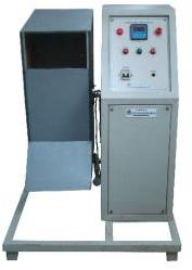
Tumbling Barrel Test Apparatus
To determine compliance with safety requirement of mechanical strength of test samples Features Repeated falls from a height of 500 mm Revolution speed of the barrel: 5 RPM Self-contained compact unit that can be floor mounted Laminated wooden barrel mounted on a sturdy support frame Motorized operation enables ease of use Rotation Speed of five RPM, providing a fall rate of ten falls per minutes Steel base plate fixed at both ends of the barrel as specified in the standards Digital pre-set four digits counter with bright LED dual display, membrane keypad selection and battery back-up to memorize count value in case of power cut-off Audible / Visible ‘Test’ indication Transparent acrylic sliding cover allows easy loading and unloading of the test sample, and allows inspection during the test. Cover can be locked during the test Two castor wheels and one adjustable foot provide mobility as well as levelling facility Non-contact proximity sensor ensures reliable operation Barrel JOG Switch to bring the barrel to upright position after end of Test Compact Size, can be floor mounted Specification It consists of a wooden barrel, with a shape and dimensions as specified in the relevant standard. The barrel is rotated about its central axis by a motor such that its speed is five revolutions per minute.
...more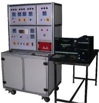
TEST SET UP FOR COMPLETE LED LUMINARY FITTING
SCR ELEKTRONIKS make PC based ELECTRICAL SAFETY TEST EQUIPMENT for LED LUMINARY is an application specific, customised & automatic test bench for testing of LED based LUMINARY. Features The test system comprises of: 1. Earth Bond Tester: An AC current source (maximum 6V) settable between 2 & 20A is provided (pre-set to 10A) for this application. The resistance is calculated and displayed on meter. The resistance limit is settable with pot-meter, normally 1Ω. 2. High Voltage Tester: This is for Hipot Test from 0 to 1.5kV or 0 to 4kV selectable by switch. The tripping currents are 2, 5, 10, 25 and 50mA can be selected through switch. Fault Indicator to confirm test results on bench and same is available in TestWare. 3. Insulation Resistance Tester: This test is conducted at 500V DC, with measuring ranges from 0.1MΩ up to 20MΩ and selectable tripping levels- 1, 2, 5, 10, 20MΩ. Fault/Pass Indicator to confirm test results is available in on bench & in TestWare. 4. Leakage Current Tester: This test is carried out simultaneously with Performance Test at nominal voltage. The test is carried out for both supply polarity. 5. Lamp Burning (Glowing) Test: The voltage is increased gradually and the value at which the lamp glows is noted. 6. Performance Test: This test includes: a. Limiting Low Voltage Test: This is for measurement of DC output (voltage & current) at specified low input voltage. b. Limiting High Voltage Test: This is for measurement of DC output (voltage & current) at specified high input voltage. c. Nominal Voltage Test: This is for measurement of DC output (voltage, current & power) at nominal input voltage, AC input voltage, current, power, and power factor. The equipment has a Programmable (Solid State) AC Voltage Source. This is a programmable voltage source with settable voltage & settable rate of rise of voltage between 20V & 350V at 40, 50 or 60Hz. The output voltage, current, wattage and power factor are displayed on meter and are available on PC based TestWare. This source is used for: Performance Test at Limiting Low Voltage, Limiting High Voltage & Nominal Voltage a. The “limiting low voltage” is adjusted and DC current & voltage is measured, stored and compared with set limits. b. The “limiting High Voltage“ is adjusted and DC current & voltage is measured, stored and compared with set limits. c. The “Nominal Voltage” is adjusted and DC current & voltage is measured, stored and compared with set limits. The leakage for both the polarities is measured during this test.
...more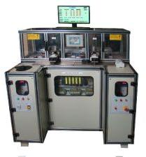
TEST PANEL FOR ROUTINE TESTING
Pneumatically controlled fixtures for loading and unloading with user safety PC based test operation, control and data keeping Indication lamps and relevant metering: To display the applied High Voltage The test section is housed in transparent cover for user safety: Loading and unloading of RCCBs is automated without opening the front cover Isolated section for HV circuit for safety of maintenance personnel Ideal for routine testing for RCCBs Cabinet: MS fabricated steel with extruded aluminum
...more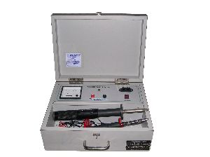
TEST FINGER APPARATUS
1. Test Finger with spring loaded arrangement 2. Flexible Test Finger 3. Control Panel for Test Finger Apparatus
...more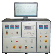
LED Driver Test Equipment
The test equipment is a solution for manufacturers & OEMs to test the LED Driver on manufacturing line. Features 1. Automatic Operation 2. Fast Operations. The complete test gets complete before 20 seconds. 3. The Efficient Software evaluates and stores the result in an efficient manner. 4. No need of any load required. The user may use one the PCB samples to act as a load.
...more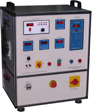
Temperature Rise Test Set Up
Servo controlled regulation against line voltage fluctuations Programmable current source (Servo controlled voltage source) Micro controller based Preset timer to enable the user to digitally set On-time. Digital display of voltage, current, temperature and time Manual / Auto / PC Based Option gives the user a flexibility to test the system in any test mode PC based data logging: Following curves can be plotted / compared on PC: Test current, millivolt drop measurement, temperature and time
...more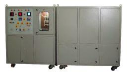
Temperature Rise Test Bench
Stand alone unit after initial configuration of test parameters: The panel is capable to generate accurate test results for a continuous period of 28 days as required in the 28 days test Cooling shall be provided by means of optimally placed Exhaust fans distributed all over to remove the hot air generated inside the panel cabinet Power Loss Measurement available as an extra feature Single / Three Phase operation possible Servo controlled mechanism to control current (+/- 1%) against incoming fluctuations Microcontroller based timer unit for quick and easy user interface and automated operation Inductors with tapping for each range will be provided for maintaining the open circuit voltage to 30V. This eliminates energy wastage during test User may opt for test bench with heating chamber for testing at 60 o C. Specifications Total current range 0 to 200 A 0.5A to 125A at 30V open circuit Voltage CT range 2A, 5A, 10A, 25A, 50A, 100A,200A 50 / 60 Hz operation as per incoming line frequency Overall accuracy of the panel is better than class 1.0 Digital Temperature Indicator with input from thermocouple Digital Volt Meter with 5 ranges (200mV, 2V, 20V, 200V, 250V) to measure open circuit voltage & mV drop across MCB Digital Ammeter with CT (Indication on servo controller) Class 1 Accuracy
...more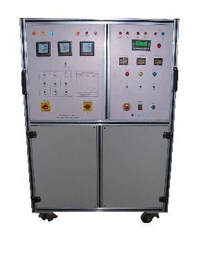
SWITCH ENDURANCE TEST BENCH
The SCR Elektroniks 3 station Switch Endurance Test Bench is designed to verify the endurance testing of household and rocker switches as per IEC 60669, IS 3854 and BS EN 60669. Typical switch ratings covered are for the entire range (typically 6 – 45 A) for both 3 phase and single phase loads. The tests included (that can be customized) are as follows: 1. Normal Operation (Referred to as Cl 19.1 in IEC 60669, IS 3854 and BS EN 60669) 2. Making and Breaking Capacity (Referred to as Cl 18.1 in IEC 60669, IS 3854 and BS EN 60669) 3. Temperature Rise (Referred to as Cl 17 in IEC 60669, IS 3854 and BS EN 60669) 4. Fluorescent Lamp Load (Referred to as Cl 19.2 in IEC 60669, IS 3854 and BS EN 60669) 5. Tungsten Filament Lamp Load (Referred to as Cl 18.2 in IEC 60669, IS 3854 and BS EN 60669) Features Stand-alone unit after initial configuration of test parameters: The panel is capable to generate accurate test results even after days of continuous operation with no loss of data. Single / Three Phase operation possible Servo controlled mechanism to control current (+/- 1%) against incoming fluctuations CT range selection for current measurement accuracy Load selection is selector switch based: Quick and easy PLC based timer unit (Siemens Logo) for quick and easy user interface and automated operation: Easy setting of parameters such as on time, off time, no. of cycles and threshold consecutive contact weld, contact open cycles Accurately designed iron core inductors (Optional air core inductors as per customer specifications) for circuit parameter accuracy Specially designed fixture for safe operation with operator safety in view Cooling shall be provided by means of optimally placed Exhaust fans distributed all over to remove the hot air generated inside the panel cabinet: This avoids change in circuit parameters as a result of over heating of loads Ceramic core wire wound resistors with enamel coating: This ensures best quality of resistors that have a favourable resistance v/s temperature rise graph enabling operation for an elongated duration with accuracy Temperature rise test can be integrated with the main endurance test PC based option available: Complete PC data logging and control plus online plotting of temperature rise graphs
...more
SWITCH ELECTRIC ROUTINE TEST BENCH
The SCR Elektroniks Switch Di-Electric Test Bench is designed to verify the high voltage testing of household and rocker switches (SPST and SPDT) as per IEC 60669, IS 3854 and BS EN 60669. The system employs Siemens PLC to carry out the test sequence and test parameter (timing) setting. The di-electric strength test is referred to as Clause 16.2 in the following standards: 1. IEC 60669 2. BS-EN 60669 3. IS 3854. Features Stand-alone unit after initial configuration of test parameters: The operator just pushes a push button for initiation of the test sequence User friendly Front control panel for easy setting of parameters Siemens PLC for completely automated operation Specially designed fixture for safe operation with operator safety in view User selectable threshold mA leakage current Diagnostic mode for periodical debugging and diagnostic check of machine / controls and fixture Mounted on castor wheel
...more
SPRING HAMMER IMPACT TESTER
The Spring Hammer consists of three principal parts : the body, the striking element and the release system. The body comprises the housing, the guide for the striking element, the release mechanism and all parts rigidly fixed thereto. The striking element comprises the hammer head, the hammer shaft and the cocking knob. The mass of this assembly is 250 g for severities not exceeding 1 J, and 500 g for 2 J. The pressure to release the striking element will not exceed 10 N.
...more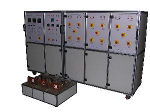
SOCKET ENDURANCE TEST BENCH
The SCR Elektroniks 3 station Socket Endurance Test Bench is designed to verify the endurance testing of sockets as per IEC 60884, IS 1293 and BS 1363. Typical sockets ratings covered are for the entire range (typically 6 – 32 A) for both 3 phase and single phase loads. Features Stand-alone unit after initial configuration of test parameters: The panel is capable to generate accurate test results even after days of continuous operation with no loss of data. Single / Three Phase operation possible Servo controlled mechanism to control current (+/- 1%) against incoming fluctuations CT range selection for current measurement accuracy Load selection is selector switch based: Quick and easy PLC based timer unit (Siemens Logo) for quick and easy user interface and automated operation: Easy setting of parameters such as on time, off time, no. of cycles and threshold consecutive contact weld, contact open cycles Accurately designed iron core inductors (Optional air core inductors as per customer specifications) for circuit parameter accuracy Specially designed fixture for safe operation with operator safety in view Cooling shall be provided by means of optimally placed Exhaust fans distributed all over to remove the hot air generated inside the panel cabinet: This avoids change in circuit parameters as a result of over heating of loads Ceramic core wire wound resistors with enamel coating: This ensures best quality of resistors that have a favourable resistance v/s temperature rise graph enabling operation for an elongated duration with accuracy Temperature rise test can be integrated with the main endurance test PC based option available: Complete PC data logging and control plus online plotting of temperature rise graphs
...more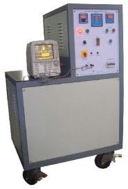
SHORT TIME OVER CURRENT TEST EQUIPMENT
Is used to measure and analyse the influence of short-time over currents on energy meter. This test is described in various standards for energy meters such as IEC 62053, IS 13779 and so on. Features The STOC 01/02 briefly consists of a power circuit and a control panel. The power circuit feeds the ‘overcurrent’ to the UUT. The control panel provides the user interface to adjust the parameters as per the requirements of the standards and the UUT. The Power circuit in the Short-time Overcurrent Test Equipment contains a variable voltage source that has capacity to source high current value for short time.
...more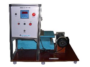
SHOCK TEST APPARATUS
Vertical Height Adjustment up to 250 mm (Normal Distance 180 mm) Horizontal Distance Adjustment from 150 mm to 250 mm (Normal Distance 180 mm) Spring Constant: 25 N / mm Motorized arrangement to adjust dropping height = 40 mm Digital pre-counter is provided to count the number of drops
...more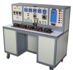
Relay Test Bench
The bench has a facility to test multiple relays simultaneously and independently of each other in a modular fashion. Each test station has its own SMPS based current source (that sets the desired test current instantly), a pneumatic fixture, a micro-controller based logic controller to control the current and a small NO / NC indicating lamp to instantly indicate to the operator the status of NO / NC contact. Features The system is available with individual current source available in different ranges from DC 0.2A to 40 A/24V max (with regulation of 0.2%). Specially designed jigs for ease and operator safety (can be integrated on an automated assembly). No risk to operator as max voltage is 24V DC; does not require skilled operator. Pneumatic fixtures to quick load/unload all stations by one operator. Customizable to suit any production load : 1 Station, 2 Station ...... 48 Stations. Reporting for Data Analysis. Modular design for easy maintenance & to ensure zero break down. Lower power consumption as each station goes in sleep mode automatically after trip.
...more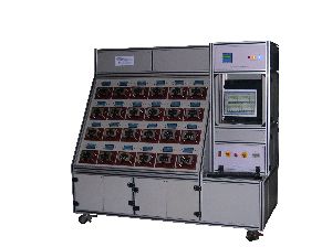
Relay Heating Routine Test Bench
The SCR Elektroniks make relay heating test bench is a low cost heating test bench to test the continuity of bimetallic overload relays against over current. Features Easy to use low cost bench Servo controlled current source for line and load regulation (1%) Continuity Indication Manual Operation possible In built timer to pre set the total time of the test: Universal for all stations NO / NC indication on each fixture
...more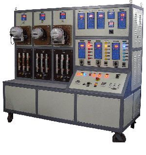
phantom loads
Subject an energy meter to a large variety of combinations of load with respect to its voltage, current and power factor Features Power Source: 0 to 300V AC, 0 to 50A with Power Factor adjustment facility from 0.1 Lag to 0.1 Lead through unity with seven steps Digital Voltmeter: 0 to 300V AC Digital Ammeter: 0 to 1.000 Digital Power Factor Meter: 0.1 Lag - Unity - 0.1 Lead Mains ON MCB: This is TPN MCB of 4A Rating provided for switch ON/OFF Adjust Voltage Variac: This is Single Phase / 2A variac provided for adjusting the output voltage from 0 to 300V Adjust Current Variac: This is a Single Phase / 2A variac provided for adjusting the load current from 0 to the range selected by switch Set Power Factor Switch: For adjusting the power factor with seven steps is provided. With this coarse adjustment of power factor can be done Adjust Power Factor Fine Variac: This is a Single Phase / 2A variac provided to fine tune the power factor Output Terminals: Two terminals for voltage & two terminals for current are provided at the front panel to connect the `Meter under Test' to the test set-up For testing 3-phase energy meters, 3 such set-ups are housed in a single unit This set-up is used for production test of energy meters. It is normally multi-station, such as a 40 station test set-up. Three Phase Phantom Loads Salient Features: Voltage Source: Adjustable 0 - 300 Volt/600VA with Static phase shifting arrangement to obtain 90° lag through unity to 90° lead with respect to Current Source. Facility to switch to 70% and 120% of set voltage will be provided for creep test. Current Source: 0 - 100A adjustable in steps with switch and fine by variac; Switching arrangement will be made to get 100%, 400%, 500%, 600% and 800% of basic setting. Also, arrangement will be provided to select 0.4%, 5%, 10%, 20%, and 100% of setting for carrying out Starting Current Test. Digital Ammeter 3 & 1/2 digit Class 1 Digital Voltmeter 3 & 1/2 digit 0 - 300V class 1 Power factor meter to read phase angle between 90° lag - Unity - 90° lead. Line frequency Indicator 40hz to 60hz Outputs on insulated terminals
...more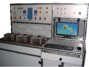
PC BASED MOTOR STARTER ROUTINE TEST BENCH
3 relays can be at a time checked for continuity and reliability to heat. (The number of relays to be tested can be customized). The panel can work in Manual mode: Here all the settings for current and primary voltage are done manually. The test would only start when the Heating Test On, dual push button is pushed ON. Timer mode: Here too all the settings for current and primary voltage are to be done manually. Here the timer is set, to enter the time, for which the current is to be passed and the test would only start when the dual start push button is pressed. PC mode, where it performs all the operations automatically using TESTWARE, without manually entering the settings again and again. If the particular station is to be left empty, then it can be bypassed using a toggle switch present on the panel. PC USB port is used for PC interface.
...more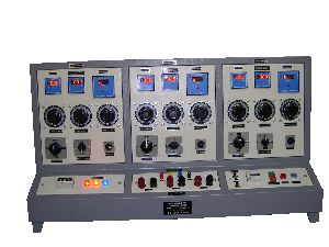
PC BASED FULL RANGE ACCURACY TEST EQUIPMENT
The bench comprises of: 1. Power Source. 2. Micro-controller based error calculation module. 3. Sensors at each station. 4. Reference meter. 5. PC with software for control and reportin
...more
PC BASED CALIBRATION BENCH FOR ENERGY METERS
Calibrating Energy meters at a time e.g. 5, 10, 20, 40, 60 or 80 resulting in speedy testing. Features Single as well as three phase energy meters can be tested Can Calibrate 80 meters at a time Customized design of test jigs (electro-pneumatic fixtures) for ease and safety of operator Customized PC based software with secured database and report generation Micro Controller based error calculation module Sensors at each station Reference Meter for testing accuracy
...more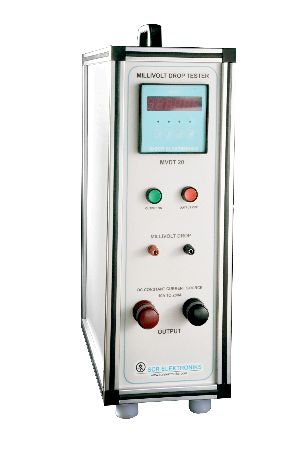
MILLIVOLT DROP TESTER
This Equipment measure Voltage drop across bus bar joints Features Microcontroller based unit Automated Operation Available Solid state DC current source from 1 A to 400 A depending on the range and model Millivolt range from 0-2000 mV Accurate adjustment of current with lesser time delay Line and load regulation of about 0.2% Compact in size Light weight and portable unit Heavy duty copper bus bars for minimal external voltage drop (error) Programmable keypad on the front panel LED Display to display test parameters and the test result PC Interface possible with software (optional) to convert test results to tabulated formats such as EXCEL
...more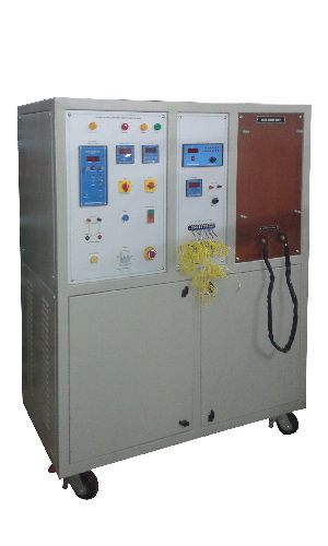
MCCB TEMPERATURE RISE HYBRID TEST BENCH
Available in multi-pole testing options Drop down menu in the software to once select the type (rating or calibre) of MCCB: Rest of the test parameters get selected automatically (User can simply jump from one type of test model to other instantaneously) IEC based test parameters automatically configured Software: NI LabVIEW based for user interface, settings selection, process control & report generation Servo Controlled Voltage Regulation ensures stable voltage at the output Pneumatic based test jigs for correct contact at terminals Generation of Reports in MS Excel format or to Print Temperature curves can be compared on a single graph Temperature Rise software module. Specifiaction 440 V, 3 phase, 50 Hz input Output current programmable up to 8000 A continuous and 20000 A short time depending upon the customer requirement at a conveniently low voltage Temperature rise as per IEC conformance / customized Test Procedure options: IEC 60947-2 / customized Pressure Required for pneumatic handling: Approximately 8-12 Bar depending on the MCCB size (for routine testing) PC provided: IBM PC / compatible make with NI LabVIEW based TestwareTM 500 VA branded UPS (optional)
...more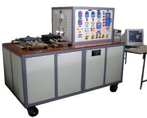
MCCB RESEARCH AND DEVELOPMENT TEST BENCH
Available in multi-pole testing options Drop down menu in the software to once select the type (rating or calibre) of MCCB: Rest of the test parameters get selected automatically (User can simply jump from one type of MCCB to other instantaneously) IEC based test parameters automatically configured Software: NI LabVIEW based for user interface, settings selection, process control & report generation Servo Controlled Voltage Regulation ensures stable voltage at the output Pneumatic based test jigs for correct contact at terminals Test results are displayed on monitor and stored against serial number or a bar code Generation of Reports in MS Excel format or to Print Exact trip current wave-form (and not a vague band) is displayed on PC Two or more curves can be compared on PC Temperature Rise module can be added as an additional option
...more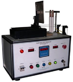
MCCB Research and Development Bench
This is a hybrid bench to integrate MCCB instantaneous tripping as well as overload tripping as per IEC 60947-2 clause 6.3.3 and custom test requirements. The system comes with TestWareTM making testing of MCCBs complete where thermal curves with can be plotted on a PC. The test jig is flexible such that different MCCBs can be tested and compared for their performance. Test system comes along with the in-built PC based software: TestwareTM. Also, test and compliance parameters can be edited and stored against a particular model such that when the MCCB model is chosen, all test parameters get adjusted accordingly. The data can be exported to spread-sheet format for analysis. Features The product is optimized to include two over current testing modules at a lesser cost thus making it ideal for manufacturers & quality engineers requiring to do research and development on the product as far as over current tripping is concerned. Available in multi-pole testing options Drop down menu in the software to once select the type (rating or calibre) of MCCB: Rest of the test parameters get selected automatically (User can simply jump from one type of MCCB to other instantaneously) IEC based test parameters automatically configured
...moreBe first to Rate
Rate ThisOpening Hours