
wind tunnel
This is an open circuit Wind Tunnel which provides a region of controlled airflow into which models can be inserted. The propulsion is provided by a fan at downstream of working section. The tunnel consists of bell mouth shaped entry to guide the air smoothly into settling chamber consisting of honeycomb and nylon mesh screens which filters and stabilizes the air flow. This follows working section or test section where various models can be tested. Two windows with acrylic sheet one each on either side will be provided for visual observation. Working section is followed by diffuser section, which reduces the dynamic pressure at the exit. A three -blade fan coupled with D.C variable speed motor is used to produce desired wind velocity. A thyristorised motor control is used for smooth variation of air velocity. Wooden Models Aerofoil: a) Symmetrical b) Unsymmetrical. 150mm, width and 250mm.long with 15 piezometric tapping with 0-360 degree protractor. Cylindrical Model: 75mm, dia., 250mm long with piezometric tapping and 0-360 degree protractor. Spherical Model: - 100mm, dia. Lift & Drag Indicator Lift Display: - 3 1/2 Least count: - 0.1 kg Range : - 6 kg Drag Display: - 3 1/2 Least count: - 0.1 kg Range : - 6 kg
Type : Open type Wind Tunnel.
...more
Whirling Of Shaft Apparatus
The apparatus consists of a base upon which bearing holders and drive motor can be mounted. Different bearings can be fitted in bearing block to have different end conditions, such as, both end fixed, one end fixed, one end etc. free. A variable speed motor along with speed controller is provided to drive the shaft. The unit is useful to demonstrate the phenomenon of Whirling of Shaft with single rotor. As this test is destructive, after the test shaft can not be used again, hence this unit only demonstrates the principle.
...more
VIB LAB
This set up has been designed to perform and verify the principles involved in study of vibrations. It consists of a basic frame and various components and sub assemblies designed for quick changeover and easy assembly of number of experiments in vibrations. A speed controller unit is provided for forced vibration experiments. With this unit following experiments can be conducted – Pendulum Experiments – For Pendulum a sub frame is attached to upper beam. Two Chucks and Hardened V guide is provided for carrying experiments. Experiment - 1 - Simple Pendulum To verify the relation and plot graph T² Vs. L Experiment - 2 - Compound Pendulum i) To verify the relationii) To determine the radius of gyration and equivalent length of compound pendulum.Experiment - 3 - Bi-filler Suspension( Tortional Oscillations) To determine the radius of gyration of body about the center of gravity by using relation Longitudanal Vibration - Experiment - 4 To verify the relation -and plot graph T² Vs. W Experiment - 5 Equivalent spring mass systemStudy of un damped natural vibrations of beam pivoted at one end supported by tension spring at the other end.Experiment - 6 Equivalent spring mass systemStudy of undamped natural vibration of beam pivoted at one end supported by tension spring at the other end to plot a graph of amplitude verses frequency. Torsional Vibrations - Experiment - 7 - Single RotorTo verify the relation -and study the relationship between the periodic time and shaft length. Experiment - 8 - Two RotorTo verify the relation -Experiment - 9 Single Rotor with viscous damping -To find out the damping coefficient Ct for various depths of damping drum (Immersed in oil) and to plot a graph of damping torque Vs. depth of damping drum. Experiment - 10 - Dunkerley`s RuleTo find out the natural frequency of a beam with and without load and to verify the Dunkerley`s Rule Experiment - 11 - Forced VibrationsTo study the forced vibrations for various amount of damping and to plot a graph of amplitude verses frequency. Following accessories will be supplied along with unit. - Exciter unit with FHP motor and controller. Ordinary strip chart recorder. Damper with an arrangement for changing damping.
...more
Unsteady State Heat Transfer Apparatus
The apparatus consists of a small test sphere. This sphere is heated by a hot bath, till the steady state is reached and then it is coolled in air or water / oil. During both, heating and cooling of sphere, temperature of sphere is a function of time and hence, it is a unsteady state of heat transfer process. The temperature of sphere is measured by thermocouple. The hot bath is provided to heat sphere with temperature controller to facilitate to conduct experiment at different temperatures. Specifications Test piece with thermocouples - 2 No.s of different materials. Hot bath with heater and controller. Cold bath. Digital Temperature Indicator. Service Required Floor Space - 1.5 m X 1.5 m 15 Amp., 230 V.A.C. power supply.
...more
Universal Governor Apparatus
The unit is designed to study various governors, normally used to control the speed. The unit consists of a main spindle driven by a variable speed motor mounted on a base plate. The spindle is driven by belt & pulley system. The optional governor out of four governor assemblies can be mounted on spindle. Speed control unit provided can control the spindle speed. A graduated scale is provided to measure the displacement of sleeve. The center sleeve of portal and proell governors incorporates a weight sleeve to which weights may be added. The Hartnell governor provides means of varying spring compression level. This unable the Hartnell Governor to be operated as a stable or unstable governor. The governor speed is increased in steps to give suitable sleeve movements possible. The speeds and displacements are recorded. The results may be plotted as curves of speed against displacements. Further tests are carried out by changing variables.
...more
Tilting Flume
A hydraulic flume of c/s 200x300 mm & 4000 mm length with transparent window on either sides of 1000 mm length. Sliding gates one at upstream and other at the downstream side. Screw jack for change of the slope of the flume. A Sump tank of sufficient capacity.-1250 x 1800x 500mm (1000 lit approx) Supply tank with waves damping arrangement. A 2 H.P. centrifugal monoblock pump.- laxmi make A Orificemeter with manometer to measure the discharge. Inlet/throat dimensions: 50/28 mm respectively. Trolley with point gauge for level measurement. Models supplied: A) Weirs- i) Sharp crested weir (crest length 200 mm) ii) Broad crested weir iii) ogee weir or spillway. iv) Venturi flume
...more
Stefan Boltzman Apparatus
The apparatus is designed to determine the Stefan Boltzman constant. The apparatus consists of a hemisphere fixed on a backlite plate, the outer surface is surrounded by a hot water jacket.Hot water to heat the tank is obtained from a hot water tank with heater fixed above hemisphere. Hot water jacket heats the hemisphere and this heat is transferred to a small copper test disc by radiation. This small test disc can be introduced at the center of hemisphere. A thermocouple is provided at the canter of disc to measure the temperature of disc. With the help of Timer/Stop Clock change in temperature with respect to time can be recorded. The average temperature of hemisphere can be measured by four thermocouples placed on hemisphere. Features Easy understanding of phenomenon of heat transfer by radiation. Determination of Stefan Boltzman constant. Built in timer for temperature measurement at constant intervals. Specifications Hemisphere made of copper, 200 mm dia, approx. Hot water jacket Test Disc - 20 mm dia., 1.5 mm thick, copper Hot water tank with heater. Instrumentation & Controls Multy channel Digital Temperature Indicator. Experimentation Determination of Stefan Boltzman Constant. Study of effect of hemisphere temperature on the constant
...more
Static and Dynamic Balancing Apparatus
The apparatus enables the students to experimentally balance a rotating mass system and to verify the analytical relations. The apparatus consists of a steel shaft fixed in a rectangular frame. A set of four blocks with a clamping arrangement is provided. For Static balancing, each block is individually clamped on shaft and relative weight is found out using cord and container system in terms of number of steel balls. For dynamic balancing, a moment polygon is drawn using relative weights and angular and axial positions of blocks are determined. The blocks are clamped on shaft is rotated by a motor to check dynamic balance of the system. The system is provided with angular and longitudinal scales and is suspended with chains for dynamic balancing. Specifications - Drive Motor - FHP, Universal Motor. Balancing Weights - 4 No.s with different mass for varying unbalance. Cord & Container with steel balls for relative weight measurement. Range of Experiment - 1. Static balancing of system using steel balls. 2. Dynamic balancing of a simple rotating mass system. 3. Observation of effect of unbalance in a rotating mass system.
...more
SLIP IN FLAT BELT APPARATUS
The apparatus consists of a variable speed D.C.Motor, Driving pulley and Driven pulley of equal diameter. The pullies are mounted on input shaft (Motor shaft) and output shaft. The driven pulley can slide on the base with bearing block to change initial tension in belt. Brake drum is mounted on output shaft helps to measure power output. The motor speed is varied by dimmerstat. A two channel RPM Indicator is provided to measure speeds of driven and driving pullies respectively. Specifications - D.C.Motor - 1 HP, 1500 RPM, variable speed. Driving & Driven pullies of equal diameters. Brake drum along with spring balance. Flat Belt of fixed length of following materials -a) Fabric Belt. b) Canvas Belt. c) Rubber Belt. Belt tightening arrangement. Speed Controller unit. Two Channel digital RPM Indicator. Experimentation - 1. To measure power transmitted with varied belt tensions and plotting graph of (T1 - T2) Vs. (T1+T2)/2 ie Tension Characteristics.2. To measure percentage slip at fixed belt tension by varying load on brake drum and plot graph of (T1-T2) Vs. percentage slip ie. Slip Characteristics.. 3. To measure belt slip speed and observe the limiting value of load at constant speed when the slip just starts. Service Required - 230 V.A.C. stabilised power supply.
...more
Single Cylinder Four Stroke Diesel Engine Test Rig
The unit consist of a 4 4-stroke diesel engine coupled to an Electrical Dynamometer. A water cooled brake drum along with spring balances is provided. For Electrical Dynamometer water rheostat is used as loading arrangement. SPECIFICATION: 1) Diesel engine of 5 H. P. capacity, 1500 R. P. M. 4-stroke vertical, single cylinder engine. 2) Electric Dynamometer: - A D.C. generator, with loading arrangement upto 2 Kw. Four air heater of 500 Kw. 3) For Rope Brake Dynamometer – Pully with spring balance Fuel measuring arrangement :- Consisting of a fuel tank, mounted on a strong iron stand, measurement of a fuel consumption by a burette & 3 way cock. Connecting tube, a stop watch. Cooling water arrangement:- Cooling pipes, thermocouples, measuring flask to determine the discharge of cooling water & heat carried away by cooling water. Exhaust gas temperature - digital temp. indicator Air intake measurement: - Air tank reservoir of size 0.4 m. x 0.4 m.x 0.4 m. with orifice plate, differential manometer, connecting hose. RANGE OF EXPERIMENT:- To determine the 1) B. H. P. & I. H. P. 2) Mechanical and Thermal efficiencies. 3) Air fuel ratio. 4) Specific fuel consumption. 5) Heat balance sheet. At various load conditions. SERVICE REQUIRED:- 1) Rigid foundation to absorb the vibration. 2) Water supply and piping to & from Test Rig 3) 230 V, A. C. supply with earthing connection. 4) Petrol / Diesel for Testing.
...more
Shell Tube Heat Exchanger
Shell & Tube Heat Exchangers are popular in chemical industries because they occupy less space and offer reasonable pressure drop. The apparatus consists of fabricated M.S. shell, inside which copper tubes with baffles are fitted. Hot water is obtained from a set of gysers provided with setup. This is two pass type exchanger so that hot water passes to one end of shell through tubes and returns to another end through remaining water. The cold water is admitted at the bottom of shell, which passes over hot water tubes. Control valves are provided to control the flow rates of hot water and cold water. Measuring tank is provided to measure flow rates. The unit is mounted on a sturdy stand. Specifications Shell - Material - M.S. Inner Dia. - 208mm Thickness - 6mm Length - 500mm 25% baffles at 100m distance - 4No. Tubes - Material - Copper I.D. - 13mm, O.D. - 16mm approx. Length - 500mm No. of Tubes - 24 Thermometers - 4 No. , 0 to 1000c Gysers - 3KW cap. - 2No. Measuring Tank Experimentation Determination of heat transfer coefficient for inner and outer surface of tubes. Study of variation of heat transfer coefficient with type of flow. Service Required Continuous water supply at rate of 50 lpm at constant head. Floor Space - 2m X 1m 15 Amp. , 230 V.A.C. power supply
...more
Reynolds Apparatus
The unit consists of a Acrylic tube connected to a tank. At entrance of tube a bell mouth section is provided and at the other end a valve is provide to control the rate of flow. A capillary tube is introduced centrally to the bell mouth to inject die. By varying the rate of flow the Reynolds number changes. This also changes type of flow. Visual observation of die (thread) will indicate the type of flow which can be confirmed from the REYNOLDS number computed. FEATURES Steady flow arrangement Very clear flow visualization Fine control of die thread. Accurate flow measurement & control. SPECIFICATIONS Acrylic tube (transparent) 25 mm OD / 20 mm ID of 1 meter length. Main Tank - 400X400X700 mm Constant Supply tank of 200x200x 200 Flow control valve. Dye tank and syringe Measuring Flask & stop watch for flow measurement. RANGE OF EXPERIMENT To determine the Reynolds number & hence the type of flow either laminar or turbulent. To determine upper & lower Reynolds number & velocities.
...more
Pipe Friction Apparatus
The unit consist of two pipes of different diameter. A collect tank is provided to measure the actual discharge. FEATURES Testing of two pipes of different diameters. Measurement of head loss in the pipes at various flow rates. Calculation of pipe friction at various flow rates. SPECIFICATIONS Sump Tank – 900 x 400 x 400 mm with FRP lining Measuring Tank – 300 x 400 x 300 mm with FRP lining Three pipes of 28 mm, 21 mm.& 17mm. diameter G.I. Pipe. Length of pipe 1 m. Flow control valve. Differential manometer – 400 mm Stop watch.
...more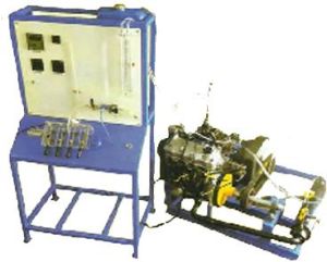
Petrol Engine Test Rig
Petrol engine test rig consisting of a multicylinder 4- stroke 4 cylinder petrol engine, developing about 10 H.P. at 1500 R.P.M. engine.The unit is accompanied with the following accessories :- ignition switch, a radiator, a self starter, a battery ammeter, a throttle control. Special arrangements by switches for cutting off ignition of each cylinder for morse test, all mounted on a suitable panel board, a battery for starting the engine, clutch arrangement.
...more
Pelton Turbine Test Rig
Pelton WheelFitted with 18 buckets, nozzle for water jet, casing with one side of perspex sheet. The turbine develops 1 HP Approx. output power.The Whole piping of pelton turbine is in G.I. (2â€) & valves are ball valves type made by brass material.witch and starter suitable for the above monoblock pump set, mounted on a panel board.
Power : 30 m & 5 H.P.
...more
Orifice and Mouthpiece Apparatus
The unit consists of supply tank along with orifice and mouth piece fixed to the tank. A pointer is provided at the discharge of orifice to demonstrate & to determine X, Y co -ordinate of jet. FEATURES An arrangement to obtain a steady or quiescent flow. An arrangement to vary the head by changing the position of over flow pipe. Piezometer tube to measure head. An arrangement to measure co-ordinate of jet. SPECIFICATION Main supply tank with orifice & mouthpiece fitting arrangement Size 400 x 400 x 600 mm with FRP lining Sump Tank – 900 x 400 x 400 mm with FRP Lining Measuring tank size – 300 x 400 x 300 mm Orifice 2 No.– Diameter of Orifice-8 & 10 mm, Mouth Piece - Diameter of mouthpiece 8 mm Length 25 mm Diameter of mouthpiece 10 mm Length 50 mm Tracer pointer with scale. Stop watch.
...more
Motorised Gyroscope
Now a days gyroscope is a very important tool used for various controls in high technology vehicles. For minimizing rolling, yawing and pitching of ship or aircraft Gyroscope is used. Balloons use Gyroscope for controlling direction. Gyroscope has applications in spacecraft, space platforms. Thus study of Gyroscope is of high importance for any Engineering student. Description - The Motorised Gyroscope consists of a disc rotor mounted on a horizontal shaft rotating in the ball bearings of one frame. The rotor shaft is coupled to a motor mounted on a trunion frame having bearings in a yoke frame which is free to rotate vertical axis. Thus the disc can be rotated about three perpendicular axis. Angular scale and pointer fitted to frame helps to measure precession rate. Features - Demonstration of relationship between applied torque and precession rate along with direction of rotation. Gyroscopic couple easily varied by weights. Precisely balanced rotor. Useful to verify the relationship - T = I.p Specifications - Disc Rotor - 30 Cm. dia., 10 mm thick approx. Drive - FHP, AC/DC Single Phase Motor. Dimmerstat to vary speed of motor. Weight Set. Range of Experiment -1) Observation of Gyroscopic behavior. ( Two Laws of Stability )2) Experimental justification of the equation T = I.p For calculating the Gyroscopic couple by observation and measurement of results for independent variations in applied couple T and precession p. Service Required - 230 Volts, A.C.stabilized supply. Tachometer 1m X 1m space, at working height.
...more
Milling Tool Dynamometer
This is simple and easy to understand set up designed to study behavior of cutting forces during Milling Operation. This is based on octagonal ring method, which consist two pairs of octagonal rings with strain gauges mounted on it. These rings are sandwiched between two plates. A machine vice is mounted on top plate to hold job to be machined. A three channel digital force indicator is provided to measure three forces simultaneously. Specifications - Mechanical sensing unit with octagonal ring set and strain gauges. Digital force indicator - 3 channel to measure three forces simultaneously. Range - 0 to 500 Kg Resolution - 1 Kg Balancing pots for initial zero setting. Machine vice to hold job. The set up is calibrated at our works with the help of standard Proving Ring.
...more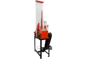
Michell Tilting Pad Bearing Apparatus
The unit is designed to provide visual demonstration and measurement of longitudinal and transverse pressure distribution over Michell Thrust Bearing. Students can vary speed, gap and viscosity of oil. It gives visual demonstration of cavitaion. The unit consists of a belt moving on two identical pulleys driven by variable speed d.c.motor. The belt passes through a oil tank and carries oil film along with. This oil passes through tilting pads and develops pressure, which is measured by manometer through pressure tapings on tilting pad. Different types of pads can be used. Specifications -Drive Motor - 0.5 HP, 1,500 RPM, variable speed D.C.Motor with speed controller. Tilting Pad - a) Convergent Type - Rectangle b) Convergent Divergent Type - Rectangular. Multitube ManometerManometer for cavitation demonstrationOil Tank - 0.5 X 0.2 X 0.2 m approx.Loading arrangement on pads.
...more
Lathe tool dynamometer
This is a strain Gauge Type two/three component Lathe Tool Dynamometer designed to measure vertical & horizontal/(radial force in case of three component) forces on tool while orthogonal cutting process. The unit consists a mechanical sensing unit or tool holder and digital force indicator. With this dynamometer, students can study the change in these forces due to change in speed, feed and depth of cut. Specifications - Mechanical Sensing Unit with Tool Holder and Tool with strain Gauges mounted on it. Digital Force Indicator - two/three channel, to read both forces simultaneously. Balancing Potentiometer for initial balancing Range - 0 to 300 Kg, least count - 1 Kg. Tool Size 12 mm The set up is calibrated at our works with the help of standard Proving Ring.
...more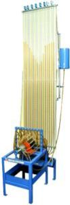
Journal Bearing Apparatus
The apparatus consists of a plain shaft encased in a bearing and directly driven by a small motor. The bearing is freely supported on the shaft and sealed at motor end. The motor speed is precisely controlled by control unit. The bearing contains twelve equispaced pressure tapings around circumference and four along the axis. All tapings are connected by light flexible plastic tubes to the manometer so that the pressure head of all sixteen points can be observed at a time. The bearing can be loaded by attaching weights to the arm supported beneath it. Specifications - Journal 50 mm dia. (Nominal) Bearing 55 mm dia. Weights 4 Adustable weights. Motor D.C.Motor Control Panel for speed control Manometer Board ( Sixteen Tube) Oil recommended - SAE 30/40
...more
Insulating Powder Thermal Conductivity
The apparatus consists of a copper sphere in which a mica heater is fitted. This small sphere is surrounded by another copper sphere and the insulating powder to be tested is filled in between these two spheres. The heat produced by heater is radially flows outwards in all directions through insulating powder. A digital temperature indicator is used to measure temperatures of Inner & Outer sphere. An ammeter & voltmeter is provided to measure heater input. By knowing heat input and temperatures, thermal conductivity of powder can be calculated. The unit is provided with asbestos powder, however any other powder can be tested with this unit. Specifications Inner sphere - copper - 100 mm. dia. Outer sphere - copper - 200 mm dia. Heater – Mica heater placed in inner sphere. Thermocouples on outer surface of inner sphere and inner surface of outer sphere. Instrumentation & Controls Digital Voltmeter - 0 - 199.9 Volts. Digital Ammeter - 0 - 1.999 Amp. Multy channel Digital Temperature Indicator. Heater Control Service Required 230 V.A.C. stabilised supply with earthing Floor space - 1.5m X 1.5 m at working height.
...more
Heat Transfer Apparatus
The apparatus consists of a small test sphere. This sphere is heated by a hot bath, till the steady state is reached and then it is coolled in air or water oil. During both, heating and cooling of sphere, temperature of sphere is a function of time and hence, it is a unsteady state of heat transfer process. The temperature of sphere is measured by thermocouple. The hot bath is provided to heat sphere with temperature controller to facilitate to conduct experiment at different temperatures.
...more
Heat Pipe Demonstrator
The apparatus enables the students to study the interesting phenomenon of heat pipe & to compare its performance with other pipes. The apparatus consists of a heat pipe made up of stainless steel, evacuated and partially filled with distilled water, a copper pipe and stainless steel pipe of same sizes. The pipes are heated at one end and water tank is provided at other end of pipes to take over heat. Thermocouples are provided along the length of pipes so that nearly isothermal operation of heat pipe as compared with other conductors can be demonstrated. Rapid rise of water temperature in tank around heat pipe demonstrates super conductivity of heat pipe as compared to copper and stainless steel pipe. Specifications Heat Pipe - Stainless steel pipe size 25 mm dia., 300 mm. long with both side closed, evacuated and filled with distilled water. Copper Pipe - 25 mm dia., 300 mm. long Stainless Steel pipe - 25 mm dia., 300 mm. long All pipes are positioned horizontal with one end heated by band heater and water tank at other side. Thermocouples are provided along the length to all pipes. Instrumentation & Control Digital Voltmeter - 0 to 199.9 Volts. Digital Temperature Indicator. Heater Control Service Required 230 V.A.C. stabilised supply with earthing Floor space - 3.5 m X 1 m at working height.
...more
Waste Heat Recovery System
Production of chilled water (12oC 6oC) for air-conditioning, industrial refrigeration, process cooling etc.Heat pumps for energy recovery in urban heating, hot water production and heating in industrial process.Uses of any thermal energy – hot water, steam, superheated water, gas, oil, coal, recovered heat, etc with excellent efficiency.A clean, reliable process, which satisfies the pollution and safety standards and uses Lithium Bromide, a stable and non-toxic salt instead of CFC’s or Ammonia. The materials are selected to ensure durability and compatibility with the types of fluids used and external conditions.
...moreBe first to Rate
Rate ThisOpening Hours
Share your Correspondence Details to receive messages from Technolab Associates