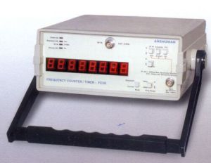
Digital Frequency Counter Demonstrator SE-805
Get Price Quote
Product Category : Electronics Measuring Instruments Demonstrator (Series : 800)Product Name : Digital Frequency Counter Demonstrator Model No. : SE-805Product Details : This has Built-In DC +5V/±12V/500mA fixed power supply, on board sine wave input signal generator with variable frequency upto 100KHz and variable amplitude upto10 Vp-p, the circuit uses associate circuitry of Schmitt trigger, driver, PLL frequency multiplier with logical & BCD Counter circuit to drive the LED Seven segment displays to indicate the frequency of applied input signal, Indication on three CC LED Seven segment Display, Frequency counter range 100KHz maximum, complete setup with maximum test points. Objectives : To Study the Principle of Digital Frequency Counter. To observe and note the output frequency on LED Seven segment display w.r.t. the applied variable input signal frequency. To compare the Observed (Practical) value with applied theoretical value. Accessories Included : Set of Patch Cords, Operating Manual

Frequency Counter
Get Price Quote
Best Deals from Electric Counter

Infrared Object Counter With Alarm
Get Price Quote
Infra-Red Object Counter With Alarm can be installed at the entry gate to count the total number of people entering any venue. For example, it can be used at the railway stations or bus stands to count the people arriving per day or week. Infra-Red Object Counter With Alarm uses an infrared transmitter-receiver pair and two 7-segment displays for counter display. Infra-Red Object Counter With Alarm works even in the presence of normal light. The maximum detection range is about two meters. No focusing lens is required. About the Circuit : The transmitter is built around IC1, which acts as an oscillator. The frequency of oscillation is determined by timing components designed around R2/R3/P1/C2.When power is on, pulse at junction of C1-R1 resets IC1 and oscillation starts. The output at pin7 given to transistor T1 which, drives IR LED denoted by D1, transmits IR radiation, which are received by IR sensor used in receiver circuit. Receiver Circuit : The receiver circuit is designed using IR sensor, transistor T1, timer IC1, which act as a one shot multivibrator. The output of IC1 is given to transistor T2, which drives buzzer. The transmitter and receiver units are aligned such that the IR beam falls directly on the IR sensor. As long as IR beam falls on the sensor, its output remains low, T1 does not conduct and trigger pin2 of IC1 remains high. When anyone interrupts the IR beam falling on the sensor, its output goes high to drive transistor T1 into conduction and pin2 of IC2 goes low shortly. As a result, IC1 gets triggered and its pin3 goes high, transistor T2 conducts and buzzer raises an alarm. Also IC3 being a decade counter receives clock pulse at pin1. It starts counting, which is shown on 7-segment displays. At every interruption, counter increases by one. You can also reset the counter by pushing switch S1. You can count maximum 99 interruptions. After 99 interruptions, counter gets reset to ‘00’.

Impulse Counters
Get Price Quote
Impulse Counters, RF Power divider, degaussers

Pulse Counter
Get Price Quote
Pulse Counter, Forklift Battery Charger, Universal Input Output Card