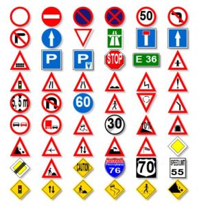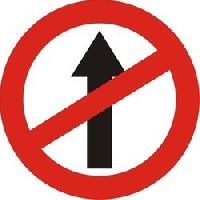
traffic signs
2,200 Per Piece

route indicator
200 Per Piece
Best Deals from Traffic Signs

Reflective Traffic Sign
2,880 Per Number
10 Number (MOQ)

Modern Traffic Light Signal
Get Price Quote
The use of few ICs makes it possible to control the big traffic in modern way in your city. Our Modern Traffic Light Signal includes four set of poles having Red, Yellow, Green and Side-Green lights at each pole. At a time, Green Signal for opposite poles P1-P3 and RED signal for other two opposite poles P2-P4 ON. When the Green signal goes off, Side-Green signal illuminates for side way traffic. As the Side-Green signal of P1-P3 goes off, GREEN signal of P2-P4 and RED signal of P1-P3 becomes ON.The circuit is designed using two-shift register IC3 and IC4, which consists of each eight outputs. It controls hold on time for each signal. IC5, IC6, and IC7 are used as a buffer to isolate the output. IC1 is used as an astable multi vibrator to provide clock input to IC3 and IC4. IC2 which is a OR gate IC used to give data-in signal to IC3.About the Circuit :As stated in introduction IC3 which is a shift register has eight outputs. As we require 16 outputs for controlling the four set of poles two ICs are used. IC1 is used to give clock signal to IC3 and IC4 at pin 1 and 9 respectively as shown in circuit diagram. At every clock, pulse generated by IC1 output goes on shifting. When power is ON, IC2 provides data-in signal to IC3 at pin7. IC3 starts shifting the output. The first three outputs are used for GREEN signal, the fourth output for YELLOW signal. The next three output for SIDE-GREEN signal and the last output for SIDE-YELLOW signal. As this is, arrange for opposite two poles P1-P3, at the same time all the eight outputs are used as a RED signal for other two opposite poles P2-P4. At the last output of IC3, IC4 receives data-in signal by connecting pin2 of IC3 to pin7 of IC4. Now IC4 starts shifting the output. Ninth to sixteenth outputs generated from IC4 are used same as above, but for other set of pole.The clock pulses generated by IC1 are indicated by LED D49, whose frequency is set by preset P1. Whereas when IC2 gives the data-in signal to IC3, LED D52 glows.Calibration : It should be noted that the clock signal and data-in signal are adjusted in proper way. When power is on at first clock pulse, IC3 gets the data-in signal, which is indicated by glowing of LED D52. But the output starts at second clock pulse. When second clock pulse goes of LED D52 must also be goes off, otherwise the circuit does not work properly. This is adjusted by preset P2.LEDs color specification for four set of poles are as follows : POLE-1 : D37-Red, D34-Yellow, D35-Green, D36-Green Right POLE-2 : D33-Red, D38-Yellow, D39-Green, D40-Green Right POLE-3 : D45-Red, D42-Yellow, D43-Green, D44-Green Right POLE-4 : D41-Red, D46-Yellow, D47-Green, D48-Green Right Power Supply :The circuit requires a DC power supply of 12V. The 12V AC output from 12-0-12V transformer gets rectified by diodes D53/D54. Capacitor C10 filters the rectified signal. This rectified output is given to input of IC8, which is a 12V regulator IC. The final regulated output is applied to the circuit.

RCC Route Indicators
Get Price Quote
RCC Route Indicators, Precast Concrete Structures

RCC Route Indicator
Get Price Quote
RCC Manhole Cover, RCC Paver Tile

Traffic Sign Boards
Get Price Quote
Traffic Sign Boards, Traffic Safety Cones, Crash Barriers, blinker lamps

RCC Route Indicator
Get Price Quote
REL 400 V RCC Tiles Indicator