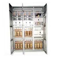
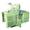

Furnace Transformer
Get Price Quote
1 Piece (MOQ)
MARSZ manufactures Arc, Submerged Arc, Ladle, Induction furnace transformers upto 10 MVA, Upto 33kV, ONAN / OFWF cooling. A high current furnace transformer is provided by having the low-voltage windings arranged in a closed delta configuration within the transformer enclosure. Bus bar terminals are mounted exterior to the enclosure for providing electrical connection with the low-voltage windings. MARSZ Furnace transformers are used to step down from voltages between 11 and 33 kV to levels of several hundred volts only. This results in massive secondary currents. As an example a 30 MVA unit at 150 V would result in a secondary current of 115 kilo Ampere. For these high secondary currents special bushings are required to connect to the bus-bars. These bushings are specified with very specific arrangements to suit the bus-bar arrangement and cooling system. Furnace bus-bars are mostly water cooled. Due to the high secondary currents and resistive losses the furnace layout is such as to limit the bus-bar length. The MARSZ furnace transformers are then located close to the furnace itself and if they are single phase units, arranged in a triangle around the furnace. This means that there is a high risk of fire, a high ambient temperature and this whole set up is located at a level associated with the third story of the building. The location above ground level encourages single phase units due to the structural limitations of the buildings. To reduce the fire risk the transformers are contained in rooms, which adds to the high ambient temperature. MARSZ Furnace transformers are very much used in a production environment. Loading of these transformers is then very close to rated values and even beyond. This demands very reliable transformers. Shutdowns due to transformer problems are frowned upon. When shutdowns occur, the problem needs to be solved quickly. This in turn calls for good accessibility of the tap changer and other parts of the transformer. Large inspection covers in close proximity to the tap changer are often specified. Due to the nature of the process MARSZ furnace transformers are specified with large tapping ranges. Thirty tap positions is not uncommon. Adding to the wide tapping range is the utilisation of the tap changer. Some users require up to 800 operations of the tap changer per day. This demands high maintainability and efforts to increase the maintenance intervals. On line tap changer oil filters are thus essential. To reduce downtime further, plug-in type diverters are specified. This allows a quick changeover of the diverter switch and an overhaul in a workshop environment with more time at hand. Another aspect of the process is the large number of short circuits that these transformers are subjected to every day. Transformers associated with open arc furnaces can be subjected to a number of short circuits per melt as the material being melted collapses across the electrodes. Bus-bar flash overs are also a fact of life on most furnace installations. To add to this peril, MARSZ furnace transformers are required to have a lower than normal impedance. This gives rise to higher over-current factors. Very robust design in terms of the transformers’ ability to withstand the dynamic effects of repeated short circuits is required. Minimum impedance values for furnace transformers of the core type are in the order of 4 – 5 %. To achieve lower values, one would need a shell type transformer. Upper levels for impedance could be any value from 10 to 24 % depending on the configuration and tapping range. Application in following industries : Chemical, Pharmaceuticals, Steel, Textile, Engineering, Plastic, Cement, Refineries, Mining, Captive Power Projects, Hydro Power Projects, Wind Mill Farms, Construction Houses, Pharma, Electrical, Electronics, Renewable Energy, Automobile.

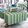
Furnace Transformers
Get Price Quote
Best Deals from Industrial Transformer
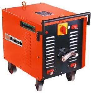
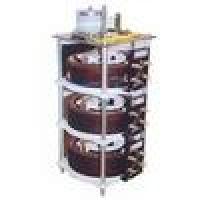
Standard AC Welding Transformers
Get Price Quote
Modern, Compact & Tropicalised Design, Reliable, Stepless Current Control, Efficient, Negligible Maintenance, Economical, Elegant & Excellent Welding characteristics. Application : General Purpose Fabrication, Medium & Heavy Structures, Machine Building, Maintenance work, Adaptable for TIG welding of Aluminium & Magnesium.

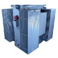
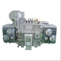
Earthing Transformers
Get Price Quote
Neutral Earthing transformers are normally provided in 3-phase system, which is without neutral and earth fault protection. Neutral earthing transformer has zig-zag (interstar) winding to achieve the required zero phase impedance. In addition an auxiliary winding can also be provided to meet the requirement of auxiliary power supply. ONAN / ONAF cooling with conventional pressed steel radiators. The range includes up to 33 KV systems and as per the site requirements. A Earthing ( zigzag ) transformer is a special purpose transformer with a zigzag or 'interconnected star' winding connection, such that each output is the vector sum of two phases offset by 120 Its applications are for the creation of a missing neutral connection from an un-grounded, 3-phase system to permit the grounding of that neutral to an earth reference point and also harmonic mitigation, as it can suppress triplet (3rd, 9th, 15th, 21st, etc.) harmonic currents, to supply 3-phase power as an auto transformer (serving as the primary and secondary with no isolated circuits), and to supply non-standard phase-shifted 3-phase power. Nine-winding three-phase transformers, typically have 3 primaries and six identical secondary windings which be used in zigzag winding connection as pictured. As with the conventional delta or wye winding configuration three-phase transformer, a standard stand-alone transformer containing only six windings on three cores can also be used in zigzag winding connection, such transformer sometimes being referred to as a zigzag bank. In all cases, six or nine winding, the first coil on each zigzag winding core is connected contrariwise to the second coil on the next core. The second coils are then all tied together to form the neutral and the phases are connected to the primary coils. Each phase, therefore, couples with each other phase and the voltages cancel out. As such, there would be negligible current through the neutral point, which can be tied to ground. Each of the three "limbs" are split into two sections. The two halves of each limb have the equal number of turns and they're wound in opposite directions. With the neutral grounded, during a phase to ground short fault, a third of current returns to the fault current and the remainder must go through two of the three phases when used to derive a grounding point from a delta source. If one phase, or more, faults to earth, the voltage applied to each phase of the transformer is no longer in balance; fluxes in the windings no longer oppose. (Using symmetrical components, this is Ia0 = Ib0 = Ic0.) Zero sequence (earth fault) current exists between the transformer’s neutral to the faulting phase. The purpose of a zigzag transformer in this application is to provide a return path for earth faults on delta-connected systems. With negligible current in the neutral under normal conditions, providing the defective load will be automatically disconnected in a fault condition, an undersized transformer may be used only as short time rating is required (i.e. the transformer can only carry full rated current for, say, 60 s). Impedance should not be too low for desired maximum fault current. Impedance can be added after the secondaries are summed to limit maximum fault currents(the 3Io path). An application example : A combination of Y (wye or star), delta, and zigzag windings may be used to achieve a vector phase shift. For example, an electrical network may have a transmission network of 110 kV/33 kV star/star transformers, with 33 kV/11 kV delta/star for the high voltage distribution network. If a transformation is required directly between the 110 kV/11 kV network an option is to use a 110 kV/11 kV star/delta transformer. The problem is that the 11 kV delta no longer has an earth reference point. Installing a zigzag transformer near the secondary side of the 110 kV/11 kV transformer provides the required earth reference point. Application in following industries : Chemical, Pharmaceuticals, Steel, Textile, Engineering, Plastic, Cement, Refineries, Mining, Captive Power Projects, Hydro Power Projects, Wind Mill Farms, Construction Houses, Pharma, Electrical, Electronics, Renewable Energy, Automobile.
Special Purpose Transformers
Get Price Quote
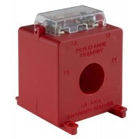
We manufacture following Special Purpose Transformers 1) Phase shift Transformers upto 200 KVA rating with phase shift of any angle 2) Synchronous Transformers 3) Voltage Contrl Trnasformers for measurement 4) Protection Transformers 5) Combined Current & Voltage Transformers 6) 12 Pulse , 24 Pulse transformers for convertors
Converter Duty Transformers
Get Price Quote
Converter Duty Transformers, Extra High Voltage Transformer

Special Purpose Transformers
Get Price Quote
Special Purpose Transformers, Pulse Transformers, switching transformers
Welding Transformers
Get Price Quote
Welding Transformers, Welding Equipment, industrial gases, Flux Cored Wires
Furnace Transformer
Get Price Quote
Furnace Transformer, Trading, chemical equipment, Bio Chemicals, end bits