
reactor transformers
Air cored series & Shunt Reactor, Upto 2 MVA , Upto 33Kv, ONAN / AN A variable transformer, reactor having a core combining at least two complete core elements with a common yoke; primary winding divided into two independently fed sets of phase coils wound in opposite direction, arranged on symmetrical legs of core elements and separated by the common yoke; secondary winding with each phase coil divided into two wound in opposite direction portions carried by symmetrical core legs, adjacent to the primary coils and separated by common yoke. The secondary short-circuited reactor winding is reduced to at least one close loop member with loop portions separated by the common yoke. The single, poly phase apparatus has at least one primary coil per set that includes a controllable device in circuit relation therewith to enable control of one primary coil relative to the other, either in current magnitude or in current phase shift. The controllable device being either a silicon control rectifier or transistor. Application in following industries : Chemical, Pharmaceuticals, Steel, Textile, Engineering, Plastic, Cement, Refineries, Mining, Captive Power Projects, Hydro Power Projects, Wind Mill Farms, Construction Houses, Pharma, Electrical, Electronics, Renewable Energy, Automobile.
...more
Power Transformers
Station & Multi-winding to suit specific needs & L.T. Transformers for generating Stations.Upto 10 MVA ,3 Phase , Upto 33Kv , ONAN/ONAF/OFAF /OFWF Cooling A power transformer is characterized by inner and outer low voltage winding sections and a high voltage winding section disposed there between. The low voltage windings are comprised of a plurality of pancake coils, and the high voltage winding are comprised of a plurality of conductor strands spirally wound for a plurality of coil layers. The low and high voltage winding sections are laterally spaced with the low voltage windings disposed in side-by-side positions and adjacent to the high voltage windings. The high voltage windings have a smaller turn height than the low voltage windings and have conductor strands of smaller gauge than the pancake coils of the low voltage windings. A Power transformer is an electrical device that transfers energy between two or more circuits through electromagnetic induction.A varying current in the transformer's primary winding creates a varying magnetic flux in the core and a varying magnetic field impinging on the secondary winding. This varying magnetic field at the secondary induces a varying electromotive force (EMF) or voltage in the secondary winding. Making use of Faraday's Law in conjunction with high magnetic permeability core properties, transformers can thus be designed to efficiently change AC voltages from one voltage level to another within power networks. Transformers range in size from RF transformers less than a cubic centimeter in volume to units interconnecting the power grid weighing hundreds of tons. A wide range of transformer designs is encountered in electronic and electric power applications Generation of electrical power in low voltage level is very much cost effective. Hence electrical power is generated in low voltage level. Theoretically, this low voltage level power can be transmitted to the receiving end. But if the voltage level of a power is increased, the electric current of the power is reduced which causes reduction in ohmic or I2R losses in the system, reduction in cross sectional area of the conductor i.e. reduction in capital cost of the system and it also improves the voltage regulation of the system. Because of these, low level power must be stepped up for efficient electrical power transmission. This is done by step up transformer at the sending side of the power system network. As this high voltage power may not be distributed to the consumers directly, this must be stepped down to the desired level at the receiving end with the help of step down transformer. These are the uses of electrical power transformer in the electrical power system. Two winding transformers are generally used where ratio between high voltage and low voltage is greater than 2. It is cost effective to use auto transformer where the ratio between high voltage and low voltage is less than 2. Again three phase single unit transformer is more cost effective than a bank of three single phase transformer unit in a three phase system. But still it is preferable to use than the later where power dealing is very large since such large size of three phase single unit power transformer may not be easily transported from manufacturer's place to work site. The high reliability of these transformers ensures maximum availability, lower maintenance costs and reduced life-cycle costs. Our ultimate goal is to exceed our customers' expectations continually by delivering the highest quality services. Power transformers comply with our quality policy by:Consistent management focus on quality; Continually improving the effectiveness of our Quality Management System;Understanding our customers goals and embracing them. Application in following industries : Chemical, Pharmaceuticals, Steel, Textile, Engineering, Plastic, Cement, Refineries, Mining, Captive Power Projects, Hydro Power Projects, Wind Mill Farms, Construction Houses, Pharma, Electrical, Electronics, Renewable Energy, Automobile
...more
Earthing Transformers
Neutral Earthing transformers are normally provided in 3-phase system, which is without neutral and earth fault protection. Neutral earthing transformer has zig-zag (interstar) winding to achieve the required zero phase impedance. In addition an auxiliary winding can also be provided to meet the requirement of auxiliary power supply. ONAN / ONAF cooling with conventional pressed steel radiators. The range includes up to 33 KV systems and as per the site requirements. A Earthing ( zigzag ) transformer is a special purpose transformer with a zigzag or 'interconnected star' winding connection, such that each output is the vector sum of two phases offset by 120 Its applications are for the creation of a missing neutral connection from an un-grounded, 3-phase system to permit the grounding of that neutral to an earth reference point and also harmonic mitigation, as it can suppress triplet (3rd, 9th, 15th, 21st, etc.) harmonic currents, to supply 3-phase power as an auto transformer (serving as the primary and secondary with no isolated circuits), and to supply non-standard phase-shifted 3-phase power. Nine-winding three-phase transformers, typically have 3 primaries and six identical secondary windings which be used in zigzag winding connection as pictured. As with the conventional delta or wye winding configuration three-phase transformer, a standard stand-alone transformer containing only six windings on three cores can also be used in zigzag winding connection, such transformer sometimes being referred to as a zigzag bank. In all cases, six or nine winding, the first coil on each zigzag winding core is connected contrariwise to the second coil on the next core. The second coils are then all tied together to form the neutral and the phases are connected to the primary coils. Each phase, therefore, couples with each other phase and the voltages cancel out. As such, there would be negligible current through the neutral point, which can be tied to ground. Each of the three "limbs" are split into two sections. The two halves of each limb have the equal number of turns and they're wound in opposite directions. With the neutral grounded, during a phase to ground short fault, a third of current returns to the fault current and the remainder must go through two of the three phases when used to derive a grounding point from a delta source. If one phase, or more, faults to earth, the voltage applied to each phase of the transformer is no longer in balance; fluxes in the windings no longer oppose. (Using symmetrical components, this is Ia0 = Ib0 = Ic0.) Zero sequence (earth fault) current exists between the transformer’s neutral to the faulting phase. The purpose of a zigzag transformer in this application is to provide a return path for earth faults on delta-connected systems. With negligible current in the neutral under normal conditions, providing the defective load will be automatically disconnected in a fault condition, an undersized transformer may be used only as short time rating is required (i.e. the transformer can only carry full rated current for, say, 60 s). Impedance should not be too low for desired maximum fault current. Impedance can be added after the secondaries are summed to limit maximum fault currents(the 3Io path). An application example : A combination of Y (wye or star), delta, and zigzag windings may be used to achieve a vector phase shift. For example, an electrical network may have a transmission network of 110 kV/33 kV star/star transformers, with 33 kV/11 kV delta/star for the high voltage distribution network. If a transformation is required directly between the 110 kV/11 kV network an option is to use a 110 kV/11 kV star/delta transformer. The problem is that the 11 kV delta no longer has an earth reference point. Installing a zigzag transformer near the secondary side of the 110 kV/11 kV transformer provides the required earth reference point. Application in following industries : Chemical, Pharmaceuticals, Steel, Textile, Engineering, Plastic, Cement, Refineries, Mining, Captive Power Projects, Hydro Power Projects, Wind Mill Farms, Construction Houses, Pharma, Electrical, Electronics, Renewable Energy, Automobile.
...more
Distribution Transformers
A distribution transformer is a transformer that provides the final voltage transformation in the electric power distribution system, stepping down the voltage used in the distribution lines to the level used by the customer. The invention of a practical efficient transformer made AC power distribution feasible; a system using distribution transformers was demonstrated as early as 1882. If mounted on a utility pole, they are called pole-mount transformers. If the distribution lines are located at ground level or underground, distribution transformers are mounted on concrete pads and locked in steel cases, thus known as pad-mount transformers. Distribution transformers normally have ratings up to 200 kVA, although some national standards can describe units up to 5000 kVA as distribution transformers. Since distribution transformers are energized for 24 hours a day (even when they don't carry any load), reducing iron losses has an important role in their design. As they usually don't operate at full load, they are designed to have maximum efficiency at lower loads. To have a better efficiency, voltage regulation in these transformers should be kept to a minimum. Hence they are designed to have small leakage reactance. Distribution transformers are classified into different categories based on certain factors such as : • Mounting location - pole, pad, underground vault• Type of insulation - liquid-immersed or dry-type• Number of Phases - single-phase or three-phase• Voltage class• Basic impulse insulation level (BIL). Distribution transformers are normally located at a service drop, where wires run from a utility pole or underground power lines to a customer's premises. They are often used for the power supply of facilities outside settlements, such as isolated houses, farmyards or pumping stations at voltages below 30 kV. Another application is the power supply of the overhead wire of railways electrified with AC. In this case single phase distribution transformers are used. The number of customers fed by a single distribution transformer varies depending on the number of customers in an area. Several homes may be fed off a single transformer in urban areas; rural distribution may require one transformer per customer. A large commercial or industrial complex will have multiple distribution transformers. Pad mount transformers are used in urban areas and neighborhoods where the primary distribution lines run underground. Many large buildings have electric service provided at primary distribution voltage. These buildings have customer-owned transformers in the basement for step-down purposes. In a secondary network system as used in urban areas, many distribution transformers may be connected in parallel, each equipped with its own network protector circuit breaker to isolate it from the secondary network in case of a fault. Distribution transformers are also found in the power collector networks of wind farms, where they step up power from each wind turbine to connect to a substation that may be several miles (kilo meters) distant. Application in following industries : Chemical, Pharmaceuticals, Steel, Textile, Engineering, Plastic, Cement, Refineries, Mining, Captive Power Projects, Hydro Power Projects, Wind Mill Farms, Construction Houses, Pharma, Electrical, Electronics, Renewable Energy, Automobile.
...more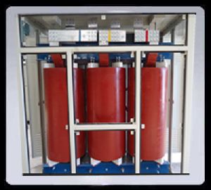
cast resin dry transformer
In cast resin dry type transformers, the complete encapsulation of primary and secondary winding in epoxy resin prevents penetration of moisture into windings. The cast resin offers very good protection against adverse ambient conditions. These transformers can work without disruption of service at 100% humidity. Due to the high grade insulation material, coils are non hygroscopic & the transformer can be switched on directly without pre-drying even after a long period of service interruption. Contrary to the conventional dry type transformers the cast coil transformers are better in respect of impulse voltage withstand strength. Higher dynamic short circuit withstands strength as compared to oil immersed and conventional dry type transformers because of fibre glass reinforced epoxy encapsulation. No partial discharges can occur during operation. The insulation material used is glass fibre reinforced with epoxy resin of class 'F' which can withstand wide temperature variation. Due to high quality insulation material the transformer is practically non-inflammable by an electrical arc, special fire protection measures are not required. Due to encapsulation of coils with cast resin the coils dimensions are stable & no coil tightening is required to maintain the short circuit strength. Also no check of oil level and electrical insulation/oil is required. This leads to saving in cost on account of maintenance. As cast resin transformers are solidly cast, problem associated with oil filled transformers like oil leakage and pilferage of oil is completely avoided. These transformers are generally smaller in dimensions and lesser in weights. The construction and installation cost for the sub-station can be reduced by adopting dry type transformers. Without fire or danger of explosion, it is possible to place the transformers near to the load centre. Also, these transformers do not need construction of special fibre brick walls or oil pits, which reduces the overall civil works. Additionally, since LT cables are not required, thers is also saving in cost on account of expensive cable laying works. Since no oil is used in these transformers, there are no chances of contamination of ground water due to oil leakage.
...moreBe first to Rate
Rate ThisOpening Hours
Share your Correspondence Details to receive messages from URJA