
Strainers cum Air Eliminator
The combination Strainer cum Air Eliminator ensures removal of solid impurities, air or vapour from the liquid before it enters the Flow Meter. It is an essential accessory for trouble free & accurate Flow Meter operation. DESIGN FEATURES Low pressure drop due to large filter element area Easy filter element removal for maintenance High venting capacity air eliminator PRINCIPLE OF OPERATION The Strainer cum Air Eliminator is fitted on C35 flow meter’s inlet side. The strainer consists of a fabricated body, having a horizontal offset between the inlet and outlet flanges. The wire mesh filter element is positively clamped by the end cover. A drain plug is provided to facilitate servicing. Liquid impurities get filtered on passing through the filter element and clean liquid flows through the flow meter. For new installations, it is advisable to first thoroughly flush lines before installing the flow meter. Periodic strainer basket inspection and cleaning is necessary to prolong the life of the flow meter. The air eliminator is mounted along side the strainer body. It consists of a stainless steel float connected to a pilot valve via multiple linkages. When air collects in the air eliminator, the buoyant force acting on the float reduces, the float drops down along with the pilot valve connected to the linkage and the air escapes through the main valve. As liquid rises in the air eliminator, the float rises to lift the pilot valve, thereby closing the air release opening of main valve.
...more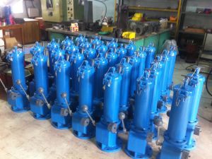
Slot Dipping Device
The Slot Dipping Device has been designed to provide convenient and safe methods for dipping, sampling and product temperature gathering functions in bulk storage tanks containing volatile and hazardous products. DESIGN FEATURES Available in 6” (150 mm) size, this device is mounted on the roofs of tanks and can be used in place of conventional gauge hatches with the following features: Negligible loss of vapor Operators not exposed to hazardous vapors No product spillage due to wiping of the tape Conforms with the requirements of Institute of Petroleum Measurement Manual Part IV Section 3.7 Accommodates thermometers manufactured to the Institute of Petroleum Specification with overall and immersed lengths of 340 mm and 65 mm respectively. PRINCIPLE OF OPERATION The Slot Dipping Device has been designed to provide a convenient and safe means of manually measuring the levels and temperature and taking samples of petroleum, petrochemical, chemical and other volatile or hazardous liquids in bulk storage tanks, in pressures of up to 40” (1016 mm) WG. The device can accommodate both heavy and light dip weights and also the Temperature and Sampling Device. The Temperature and Sampling Device has been designed to provide a means of taking samples and temperature of products stored in bulk in the petroleum, petrochemical, chemical and allied industries. When used in conjunction with the Slot Dipping Device which is suitable for pressures up to 40” (1016 mm) WG, loss of vapor is greatly reduced.
...more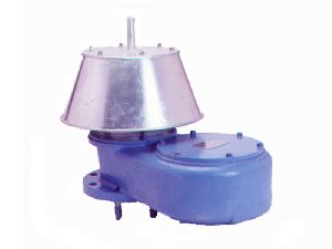
PV Breather Valves
The Series 8300 range of Breather Valves minimise vapour losses from storage tanks during operations whilst preventing internal pressure & vacuum conditions from exceeding the tank design limits. Hence both product & vessels are protected as well as tank environmental conditions. DESIGN FEATURES COMBINED UNITSSeries 8300 Pressure & Vacuum Breather Valves can be fitted in combination with Series 8350 Flame Arresters.Note – This type of installation reduces valve flow capacities and thus special sizing calculations are applicable. CHEMICAL SERVICESeries 8300 Pressure & Vacuum Breather Valves can be supplied in a range of alternative materials for chemical and/or cryogenic services and can be used with air dryers fitted at the vacuum inlet port, to protect those products which could be adversely affected by normal atmospheric air. It is suitable for wide range of services in the petroleum, chemical and related industries for land tankages only. LOW BLOW-DOWNBlow-down is the difference between opening and closing pressures. The floating diaphragm operation ensures that blow-down is minimised to 10% for pressure relief and 10-15% for vacuum relief. LOW LEAKAGECapability of the resilient diaphragm to wrap around the edge of the pallet seat. The high ratio of seating force to seating area provides a tight seal. As the pressure or vacuum rises, the relevant pallet begins to lift, but the diaphragm wrap around at the edge of the seat maintains a good seal. As the pressure or vacuum continues to rise, the pallet lifts further, but the diaphragm naturally assumes a good seal. When pressure or vacuum reaches the set conditions, the pallet opens fully.
...more
pulse transmitter
DESIGN FEATURES Flameproof enclosure High resolution of 100 pulses per revolution Two separate Pulse Trains 90 Degree Phase shift between dual Pulse O/P Level “A” Pulse security as per IP 252 & API Chapter 5 Uses Eltomatic, Denmark make Encoder (CE marked, IP65/NEMA4 certified) Very low power requirement PRINCIPLE OF OPERATION The unit consists of a precisely slotted disc, rotating through a solid state optical switch, which houses an infrared light source and a light sensitive diode. The optical switch detects the passage of the slots on the disc, as the input shaft rotates and translates them with the help of an in-built electronic circuit, into positive square wave output pulses. One revolution of the input shaft produces 100 pulses at the output. APPLICATIONS Operating remote electronic counters to indicate flow meter throughput Operating preset counters to control preset quantities through the flow meter Operating flow recording and flow rate indicating instruments Data acquisition systems
...more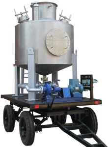
proving tanks
Proving Tanks are precision open volumetric calibrating measures. They enable on site calibration of liquid Flow Meters, Master Meters & vehicle tanks with high degree of accuracy & reliability. DESIGN FEATURES Rugged and fully welded construction Displacement tube for accurate volumetric adjustment Internal baffle plate prevents vortex formation and related trapping of air Provision to mount thermometers and level bottle for accurate liquid measurement Fixed or mobile versions with or without unloading pump and motor PRINCIPLE OF OPERATION Proving Tanks are designed and manufactured in accordance with Indian Standard IS:2341 and Manual of Weights & Measures. A Proving Tank consists of a cylindrical shell welded between two conical ends, which ensures smooth flow of liquid while draining the tank. Fitted to the bottom cone is a T-joint (where inlet and outlet isolation valves can be fitted) and a drain valve to assist in filling and draining of the tank. The top cone is fitted with a neck tube, having a conical top cover to prevent ingress of dirt in the tank. A graduated glass tube is externally fitted to the neck tube, which indicates the liquid level in the neck tube. Graduations on the tube correspond to the volume per unit height of the neck tube. The cylindrical shell has a manhole fitted with a bolted cover, which can be opened for internal inspection, painting, etc. A displacement tube arrangement is provided on the top cone to adjust the internal tank volume with the tank capacity mark on the graduated glass tube. For accurate adjustment of tank level, rest pad is fixed to the top cone for keeping level bottles. The body also has two thermowells capable of accepting mercury in steel type thermometers. A baffle plate provided at the point of liquid entry in the bottom cone, prevents swirl or vortex formation and related trapping of air in the liquid. The entire tank is erected on a sturdy steel channel frame, which can be either grouted (for a fixed Proving Tank) or bolted to a movable trolley (in case of a mobile Proving Tank). In the latter case, the trolley comes with a tow bar and leveling screw jacks. The choice of a centrifugal pump with motor to fill or drain the liquid is optional, both for fixed or mobile tanks. APPLICATIONS Calibration of field mounted liquid flow meters or master meters Vehicle tank calibration Calibration of bulk measures
...more
Piston Digital Control Valves
Piston Digital Control Valve is an electrically actuated, hydraulically operated multi-function control valve. It can be used for local as well as remote controlled batching operations with electronic batch controller. The valve also offers an in-built flow governing function. DESIGN FEATURES Fail-safe design : the valve is held closed upon loss of electric supply and/or line pressure Positive shut-off : meets ANSI Class VI for bubble-tight closure Multi-stage opening and closing : avoids static charge generation due to splashing of product in the beginning and foaming / overflow at the end, resulting in accurate delivery Low pressure drop Rectangular ports : for uniform valve response and linear control Built-in flow rate control : no need of external pilots for flow rate control, when used with electronic batch controller No diaphragm PRINCIPLE OF OPERATION The Alma Piston Digital Control Valve works on the principle of “balanced piston”. Piston is always exposed to high upstream pressure from its bottom side, whereas pressure in the piston chamber can be varied with the help of solenoid valves. When pressure in the piston chamber is equal to the high upstream pressure, the top spring acts as a differential force, pushing the piston down on the valve seat and the valve is held tightly-closed. When pressure in the piston chamber is relieved with the help of solenoid valves, a differential pressure is created across the piston. The high upstream pressure below the piston overcomes the top pressure plus the spring force and pushes the piston up, resulting in valve opening and the flow starts.
...more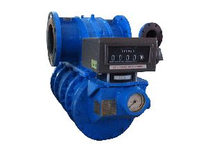
Master PD Flow Meters
Master Meters are highly accurate Flow Meters used for checking the accuracy & calibration of Flow Meters in use in their normal operating position, without the need for a Proving Tank or the breaking down of pipe work DESIGN FEATURES High accuracy and repeatability over a wide flow range Special Unit Drum attachment for higher resolution readout Stepless calibration adjustment Low pressure drop Available in fixed or mobile trolley-mounted version PRINCIPLE OF OPERATION A mechanical Master PD Flow Meter is fitted with a Rate of Flow Indicator, Unit Drum attachment and a Veeder Root Counter. The unit drum facilitates to read-off fractions of litre (or deca-litre) and the final reading can be accurately read to 0.05 litre (or 0.05 deca-litre). The unit drum, positioned below the counter, consists of a graduated circular drum with vernier scale marking. The mobile unit consists of a mobile trolley on which the Master PD Flow Meter is mounted, alongwith inlet and outlet hose connections to connect the Master PD Flow Meter in series with the field flow meter. The procedure for checking is simple. The Master Flow Meter is connected in series with the field flow meter, either by connecting it in the field flow meter’s pipe line or with the help of rubber hoses. After priming the system, counters of the test flow meter and the Master Flow Meter are zeroed and the adjusting ring of the unit drum is turned so that the zero marking coincides with any graduation on the unit drum. A fixed quantity of liquid, say 1000 litres is then passed at a constant flow rate and then respective readings on test flow meter and Master Flow Meter counters are noted down. Master Flow Meter’s fractional reading is noted from the unit drum. After applying pre-established correction factors to the Master Flow Meter’s reading, the corrected reading is then compared with the test flow meter’s reading to calculate the inaccuracies of the test flow meter.
...more
Hydraulically Operated Safety Valves
Hydraulically Operated Safety Valve has been designed as a rapid action, internal safety valve to facilitate the emergency shut-down of tanks and vessels used for the storage and transportation of LPG, Ammonia, Vinyl Chloride and other hazardous liquids stored at high pressure and usually at ambient temperatures. The valve will “FAIL-SAFE” under all conditions.\ PRINCIPLE OF OPERATION The valve is normally held closed by a heavy duty stainless steel spring and hydraulic pressure is applied to hold the valve open. When the hydraulic pressure is released, the valve closes rapidly to ensure safe shut-down in the event of an emergency. Hydraulic pressure can be released by :
...more
Gauge Hatches
Gauge Hatches have been designed to provide secure, vapor-tight, non-sparking access ports for storage tank dipping and sampling functions. CONSTRUCTION & OPERATION LOCKABLE GAUGE HATCH SIZE – 3” (75 mm)All brass construction with 3” API screwed connection. The thick elastomer ring dovetailed into the recess in the cover provides maximum vapor tightness and security against sparking.Brass body and cover. Screwed 3” API. PRESSURE TYPE GAUGE HATCH SIZES – 4” (100 mm), 6” (150 mm), 8” (200 mm)Cast iron cover incorporates a heavy synthetic rubber ring dovetailed into a recess, In 4” and 6” sizes a special moulded plastic seat inserted into the base ensures maximum vapor tightness and security against sparking. A drip ring drains condensate away from the joint face to minimize the effects of freezing. Uniform tightness at all points between the cover and the base is provided by a spherical self draining connection between the lever and the cover. Should sticking occur due to infrequent opening the handle use to screw down the cover can be removed and used to loosen the cover by continuing to rotate anti-clockwise until the cover lifts.Steel body – cast iron cover – bronze lever. 150 lbs ASA flange. SPARK-PROOF GAUGE HATCH SIZE – 8” (200 mm)Cast steel base can be supplied undrilled for welding directly to tank roof plates, or drilled for fitting to tank roof nozzle.A brass insert ring in the base is machined to give radial contact with the conical seating of the brass cover thereby ensuring an effective long term seal. Base has gauging notch located just below the insert ring.Cast steel base – brass cover – bronze handle. Flange 150 lbs ASA flat face (FF). GAUGE HATCH SIZES – 4” (100 mm), 6” (150 mm), 8” (200 mm)The aluminium base, with gauging notch, incorporates a self draining seat and has 8 slotted holes to facilitate mounting on the range of tank roof flanges listed opposite. The aluminium cover is secured to the base with a stainless steel hinge pin. A nitrile rubber “O” ring seal is fitted into the cover to provide tight closure and to cushion the effects of repeated operation. The units can accommodate service temperatures of -300C to +900C. SCREW DOWN GAUGE HATCH SIZES – 4” (100 mm), 6” (150 mm), 8” (200mm)The aluminium base, with gauging notch, incorporates a self draining seat and has 8 slotted holes to facilitate mounting on the range of tank roof flanges listed opposite. The aluminium cover is secured to the base with a stainless steel hinge pin. A nitrile rubber “O” ring seal is fitted into the cover to provide tight closure and to cushion the effects of repeated operation. The cover of the Fig. 5072 is slotted to accept the eye bolt and hand nut used for clamping the cover. The units can accommodate service temperatures of -300C to +900C.
...more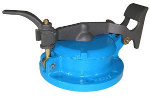
gauge hatch
Gauge Hatches have been designed to provide secure, vapor-tight, non-sparking access ports for storage tank dipping and sampling functions.All brass construction with 3” API screwed connection. The thick elastomer ring dovetailed into the recess in the cover provides maximum vapor tightness and security against sparking.
...more
Flow Meters
The T-550 is an efficient and highly accurate Positive Displacement Flowmeter. Proven design of Tri-rotor ensures minimal wear and longer service life. DESIGN FEATURES High Accuracy Lack of internal friction (No metal to metal contact) Low pressure drop Bi-directional liquid flow Suitable for wide range of liquid Meets world wide Metrological Standards Mechanical and Electrical readout Long service life PRINCIPLE OF OPERATION The T-550 flow meter has a simple and robust design. It consists of a housing and three rotors. The rotors are supported by bearings plates. The calibrator captures the rotor rotation in a calibrated manner and transmits to a counter. APPLICATIONS Truck meter /Refuellers/ Aviation Fuel Bowsers Tank Truck / Barrel Filling Blending and Dispensing in Chemical and Process industry Marine Boat loading/ unloading
...more
Flow Governors
The Flow Governor is a protective device, installed downstream of the Flow Meter, to limit the flow rate through the Flow Meter, to the maximum Meter flow rate capacity. This becomes essential when the pump capacity is greater than the capacity of the Flow Meter or when a common pump is used for more than one Flow Meter DESIGN FEATURES Low pressure drop Adjustable flow rate Compact and rugged construction A sensitive pressure differential orifice design PRINCIPLE OF OPERATION The Flow Governor consists of a body having an orifice, a spring balanced piston and a butterfly control valve. Variation in liquid flow across the orifice creates a differential pressure, which applies a downward or upward force on the piston. This in turn rotates the butterfly valve to restrict and maintain a constant rate of flow. The downward compression force on the piston is resisted by the spring tension, which is adjustable and enables accurate presetting of a constant flow rate. APPLICATIONS Single pump, multi-point gantry filling High flow regulation for meter protection
...more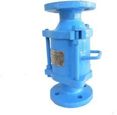
flame arrestors
Flame Arrestors prevent the passage of flames in storage vessels & along associated pipe-work systems & have applications in a wide range of industries including petroleum & petrochemicals, gas, marine & sewage treatment. FEATURES Crimped Ribbon Element DesignThe corrugated crimped ribbon design of the Series 8350 Flame Arrestor element enables it to be manufactured to very close tolerances and hence can be efficiently size selected to suit the widest range of applications and flow parameters. Pressure drop across the Flame Arrestor is very low and hence it is suitable for high gas flow rates. Weather hood option available too. Weather hoods are available for fitting to all sizes of Flame Arrestors, for use where the arrestors are mounted on outdoor, open exposed position. E.g: On vessel roofs.
...more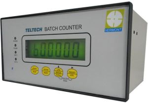
Electronic Digital Totalizer
The Electronic Digital Totalizer is a powerful flow computer, designed to meet the requirements of all types of fluid metering installations. Electronic Digital Totalizer is designed for refuellers, tank trucks, marine and process batching applications. The Electronic Digital Totalizer comes in two enclosures, first Standard Explosion proof enclosure for all hazardous area and second non-exproof (weatherproof) version SALIENT FEATURES Self-diagnostic Meter error curve linearization Alphanumeric 20 x 2 back-lit LCD display Tamper-proof and sealed calibration facility and approved by Weights & Measures department Accepts all types of interlocks for fail-safe operation Can be used with any make of flow meters and pulse generators RS-232 / RS-485 connectivity Flameproof enclosure for hazardous area application approved by PESO Weatherproof to IP-65 PRINCIPLE OF OPERATION Electronic Digital Totalizer realizes a self-test at start-up, and also periodically during operation, to ensure connectivity with external devices and systems. The Electronic Digital Totalizer can be programmed for a predetermined product quantity to be loaded prior to a delivery or as a Start / Stop system where unspecified product quantity can be delivered. In both the options, relay options are provided to control pumps and tank valves. Product delivery is started only after proper functioning of all the interlocks. The delivery commences with gradual opening of the set stop valve controlled by the Electronic Digital Totalizer. Loading operation parameters like batch quantity, flow rate can be seen on the display. During product delivery, Electronic Digital Totalizer constantly monitors the meter flow rate and linearizes the meter accuracy curve to give unmatched metering accuracy. As Electronic Digital Totalizer is designed for truck application, special features like low frequency / voltage functioning, vibration dampening, ticket printing as per customer requirement. In the case of sudden power failure during product delivery, all the process data is stored into the EEPROM memory of the equipment.
...more
Double Case Positive Displacement Meter
Double Case Positive Displacement Meters have been specially designed to eliminate the effect of line pressure on the metering accuracy. Available in a wide range of flow capacities, the Double Case design ensures a high accuracy along with ease of servicing of “in-situ’. DESIGN FEATURES Safe and rugged construction Double case design prevents distortion of measuring chamber due to line pressure fluctuations and ensures high accuracy Easy access to measuring chamber without need of removing the outer casing ensures minimum downtime Unique wear compensating vane design for sustained accuracy over a wide flow range Separate meter manifold prevents pipeline stresses from being transmitted to the measuring chamber Modular construction ensures interchangeable parts lower inventory of spares and ease of service Low pressure drop Mechanical or electronic readout PRINCIPLE OF OPERATION The Double Case PD Flow Meter consists of an outer casing with measuring capsule fixed inside. The measuring capsule consists of a bulk meter body, rotor with vane blades and two internal covers. Outer end cover and manifold, bolted to the outer casing, form a closed chamber around the measuring capsule to keep it under equilibrium pressure all the time. The product enters the Flow Meter measuring capsule through the manifold inlet and at the same time fills up the space between the outer casing and the measuring capsule. This effectively pressure balances the measuring capsule and prevents distortion due to line pressure fluctuations to ensure a high metering accuracy. The separate manifold design further enhances the performance and accuracy by preventing distortion due to pipe line stresses. The liquid on entering the measuring chamber causes the rotor to revolve by exerting pressure on the vane blades. The proximity of the rotor to the body forms an efficient seal, while the profile of the body ensures that the vane blades are guided through the measuring crescent. The vane blades divide the liquid into segments and each revolution of the rotor displaces four such segments. The rotor spindle transmits the drive through a pressure tight lip seal in the meter front cover to the pulse transmitter or the calibrating mechanism, which calibrates the meter output for a corrected counter readout. All mechanical Double Case PD Flow Meters are fitted with Veeder Root mechanical counters. APPLICATIONS Tank truck and rail wagon gantry filling Refineries and high pressure metering in petrochemical, process and chemical industries Blending and batching in lube plants, process control and chemical industries Microprocessor based automation, remote control and data acquisition systems.
...more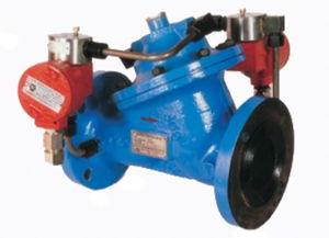
Digital Control Valves
Diaphragm Digital Control Valve is an electrically actuated, hydraulically operated multi-function control valve. It can be used for local as well as remote controlled batching operations with electronic batch controller. The valve also offers an in-built flow governing function.
...more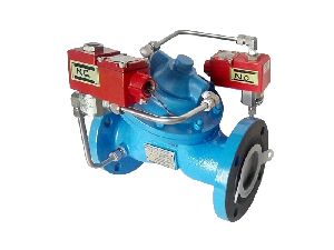
Diaphragm Digital Control Valves
Diaphragm Digital Control Valve is an electrically actuated, hydraulically operated multi-function control valve. It can be used for local as well as remote controlled batching operations with electronic batch controller. The valve also offers an in-built flow governing function DESIGN FEATURES Precision multi-stage opening and closing Fail-safe design Low pressure drop Bubble-tight seat design Flow rate control PRINCIPLE OF OPERATION The Diaphragm Digital Control Valve basically consists of a diaphragm operated main valve and two solenoid valves. Normally open (NO) solenoid connects the valve cover chamber to the upstream pressure, whereas normally closed (NC) solenoid connects the valve cover chamber to the downstream pressure. When the Diaphragm Digital Control Valve is used with an electronic batch controller, it can be digitally controlled by operating the solenoid valves through any of these three stages : when NO and NC solenoids are energized, the valve opens gradually. when NC solenoid is de-energized (keeping NO solenoid energized), the valve locks at its current position. when NO and NC solenoids are de-energized, the valve closes gradually. The operation of the valve is simple and is explained below. The total batch quantity delivered and controlled through the valve is divided into 7 stages (Refer graph) for the purpose of convenience. Initially both NO and NC solenoid valves are in de-energized condition. The NO valve applies high upstream pressure on the diaphragm, whereas the NC valve prevents this pressure from getting drained to the downstream side. The valve remains close as a result of this. Stage 1Both NO and NC solenoids are energized. NO valve now restricts the high upstream pressure from entering into the cover chamber. NC valve permits the pressure above the diaphragm to vent to the low downstream pressure. This creates a differential pressure across the diaphragm, the high upstream pressure acting from below the diaphragm opens the main valve and allows the flow to start through the valve. Stage 2As the flow rate reaches predefined value (set in the batch controller as “Low Flow Start”) the NC valve is de-energized. This prevents further draining of the chamber and locks the valve at this flow rate. Initial delivery at slow speed avoids splashing of product and also avoids the generation of static charge. Stage 3When sufficient quantity is delivered at the slow speed, the NC valve is energized again. This allows further draining of the chamber and hence increases the flow. Stage 4When the flow reaches to the maximum level (set in the batch controller), the NC solenoid is de-energized. This maintains the constant high flow rate for the remaining batch. During this stage, the flow rate control is done by the batch controller. When a number of flow meters are connected to the same pump, stopping (or starting) one or more meters increases (or decreases) the flow rate at the remaining meters. When the flow rate increases, the NO solenoid is energized momentarily. This injects some high pressure in the cover chamber and makes the valve to throttle in order to maintain the set flow rate. If the flow rate decreases, the NC solenoid is energized momentarily. This allows slight draining of the chamber and allows the valve to open further in order to maintain the set flow rate. Stage 5At the end of the batch, the NO solenoid is de-energized. This injects high upstream pressure into the cover chamber and throttles the valve. Stage 6When the valve throttles sufficiently to achieve the predefined slow closing flow rate (set in the batch controller), the NO solenoid is energized. This maintains the uniform flow rate. Stage 7When the batch quantity is delivered, the NO solenoid is de-energized. (NC solenoid is already de-energized.) This applies high upstream pressure into the cover chamber, which makes the main valve to close completely to achieve bubble-tight shut-off. Note: The number of stages during opening and closing are programmed in the batch controller and can be as many as desired. One stage during opening and two during closing are recommended. Caution: Sufficient pumping flow rate should be available to achieve the flow parameters set in the electronic batch controller. In the absence of this, there are chances of delayed response in closure, resulting in valve over-run.
...more
Bulk Air Separators
Air Separators efficiently separate & remove air or entrained gas from liquid products before they are metered. This is an essential requirement of any volume metering system for achieving a high measurement accuracy DESIGN FEATURES Rugged construction High venting capacity air eliminator Large liquid settling volume with internal baffles PRINCIPLE OF OPERATION An Air Separator consists of a mild steel cylindrical tank supported on a stand. The unit has a large cross-sectional area, which slows down the flow of liquid. An internal baffle plate arrangement assists any entrained air or gas to coalesce and separate to the top of the tank, where a high venting capacity air eliminator is fitted. The air eliminator consists of a stainless steel float connected to a pilot valve via multiple linkages. When air collects in the air eliminator, the buoyant force acting on the float reduces, the float drops down along with the pilot valve connected to the linkage and the air escapes through the main valve. As liquid rises in the air eliminator, the float rises to lift the pilot valve, thereby closing the air release opening of main valve. APPLICATIONS Removal of entrained bulk air or vapor from the metering system pipeline.
...more
Manhole Cover
The Emergency Vent is an economical solution to the present day emergency venting requirements. It is not intended as protection against an internal explosion, but to prevent excessive vapor pressure rise in the event of an external fire. It is available for use in normal, chemical or low temperature service.
...moreBe first to Rate
Rate ThisOpening Hours