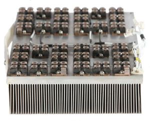
power module
Get Price Quote
The high power density and efficiency of the Power Modules of DSA series Power Amplifier is the heart of the system. These modules can use MOSFETs or IGBTs as their primary switching devices and can be coupled with numerous types of loads varying from resistive to inductive. As they are designed in a Class-D Full Bridge configuration, their operation is very similar to that of a buck converter. At output voltages lower than the input voltage, output current can be higher than the input current, as long as the input power is equal to the sum of output power and losses. Every power module is rack mounted and features a wire free design implemented using copper bus bars instead of wires. This ensures that our power module never faces any issues pertaining to loose or damaged connection. Each power module of the DSA series has a built-in PWM generation and management. These modules are stacked in master slave configuration for their parallel operation in the amplifier. PWM in paralleled modules is synchronised through master clock and a current feedback network is also implemented for precise current sharing amongst modules. Three-sigma design ensures peak current capability for continuous random operation, without affecting the life of the power device. Major Sub Systems of the Power Module are: Driver Section Driver section of the Power Module provides the necessary gate pulse to switch the conduction state of power devices from on to off and vice versa. A galvanic isolation-based gate driver circuit provides gate signals with negligible propagation and time delays. The final stage of the driver has a totem pole circuit in push-pull configuration for fast charging and discharging of the gate capacitances of the power devices at high frequencies. In a multiple module system, one module is master and the rest are slaves. The driver section of the master module generates the clock that is followed by every module in that system. This syncs all the PWM signals and reduces the final output ripple. The driver section also has two feedback networks. First is a voltage feedback to ensure output waveform is proportional to input waveform. Second is a current feedback to ensure equal current is drawn from every module in a system. Power Section We are connected in full bridge configuration and mounted on a common heat sink. The integral cooling fans ensure safe thermal operation. Each half of the bridge switches at modulated frequency such that the duty cycle varies at input signal rate. Each side is driven out of phase so that an amplified PWM signal appears across the bridge output. An array of heat sensors and two dedicated current sensors ensure the safety of this section. They are factory set to respond to the absolute maximum limits of the devices to ensure their safety in the event of a malfunction. Feedback Section Voltage feedback from the output terminal of the power section (within the output filter) to the PWM controller makes a flat response Power Amplifier. The loop incorporates DC and high frequency derivative feedback. An integrator in the loop provides linear gain and low harmonic distortion. Overall current of the power module is sensed by a non-contacting sensor which is used for the purpose of tripping and current sharing. Filter Section Sufficient attenuation to high frequency is done by LC filters to get a pure amplified output. The major part is a combination of inductor and low ESR high frequency capacitors. The final stage of the filter section contains capacitor network for minimising any noise and electromagnetic interferences along with the zobel network for impedance matching.