
Vibration Controller
Sdyn’s Vibration Controllers are tailored in 4/8/16 channel configuration to bring users the most advanced and complete range of vibration testing solutions. Our Vibration Controllers are compatible with any make of amplifier and shaker combination available worldwide. These controllers are perfectly suitable to perform vibration testing in all segments of the industry including defence, space, automobile, seismic, field equipment and consumer electronics. Coupled with analysis and documentation tools, our Vibration Controller makes the complete vibration system user friendly and an ideal means for checking the performance and reliability of your product against hazardous vibration environment to which your product would be exposed during usage. Our Vibration Controller can drive the complete range of electro-dynamic and servo-hydraulic shakers for single axis and multi-axis control applications in single and multi-shaker configurations. Sdyn’s Vibration Controllers employ high speed Digital Signal Processing (DSP) technology, low noise hardware design, optimised vibration control algorithms and high speed data transfer protocols. The software and firmware are based on multi-tasking topology with close-loop control operation between DSP and PC. This ensures true efficiency of real-time control with timely correction in input excitation to counter sudden change in response of the test system. We provide powerful features, high performance, greater than 110 dB of dynamic range and control frequency range up to 20 kHz, besides providing test engineers easy-touse application software packages. These Vibration Controllers are available with 4 to 16 input channels and are consistently modified/ upgraded to meet the demand of the latest vibration testing needs. Bundles of application software and embedded functions are specifically designed to work together so as to offer the best loop time and stable control during vibration testing. Our Vibration Controllers have the capability for making independent measurements of transfer functions and spectra of all the channels in use during vibration testing. These measurements may be independently scheduled at any time during the test and can be specifically set for analysis. Test data can be exported or imported into our software in all popular formats. Sdyn’s Vibration Controllers can be interfaced with any desktop or laptop running on Windows through USB or Ethernet interface.
...more
LTH control application
TTH control application provides a library which can be used to create a waveform like sine, chirp, beats and white noise signal. TTH can also play a short recorded data form field to simulate a transient or a pulse. Uses: Reproduction of recorded data form field on laboratory shaker system Door slam testing can be conducted with TTH control application
...more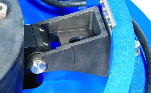
Suspension System
As the movement of the armature is based on magnetism, no physical contact is established with the shaker body. The armature is freely suspended in the air and without any suspension or auto centering system, it will sit at the bottom of the shaker. To achieve full displacement of the shaker, its armature should be centered. At Sdyn, we have multiple designs to center the armature based on customer specifications and test requirements. Our standard design utilises four sets of rolling struts spaced 90 degrees apart. Rubber bush and cam bolt is assembled inside each rolling strut to create mechanical stiffness which keeps the armature centered. Our long stroke design utilises four sets of rockers spaced 90 degrees apart. Rocker offers no mechanical stiffness and the armature is centered via DC from the amplifier. Both designs also utilise an internal load support bearing along with an air diaphragm to assist in the centering process with heavy load mounted on the armature.
...more
Sine Control Application
Sine Control Application provides all excitation energy at a single frequency. It generates analog signal with the help of programmable sweep parameters. Sine control application is most applicable to measure the dynamic response of any Unit Under Test (UUT) Uses: Fatigue and Durability test at a single frequency or swept across a frequency band Characterisation of the structural dynamics of the UUT
...more
Shock Response Spectrum
Shock Response Spectrum testing provides the ability to synthesize a complex waveform that can be applied to a shaker in a controlled manner. It varies from Classical Shock as it provides maximum achievable response in a single degree of freedom to a given transient signal. The severity of Shock test is maximised using SRS techniques. Uses: Qualification of equipment sensitive to seismic activity like Nuclear Reactor A military aircraft taking off or landing on a ship – a high level and complex shock is induced in all the equipment while the engine is working
...more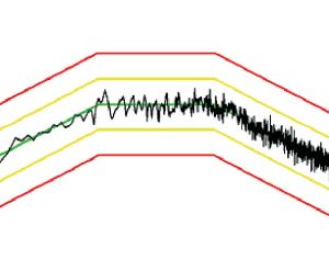
Random Control Application
Random vibration generates real word vibration environment which excites a combination of frequencies at any given instance. Due to the simultaneous generation of all frequencies within the specified frequency band, it is also called accelerated testing. Data to be recreated in represented in ‘g2/Hz’ vs. ‘Frequency’ format. Uses: Production test, stress screening, prototype testing and qualification of products Field measurement replication
...more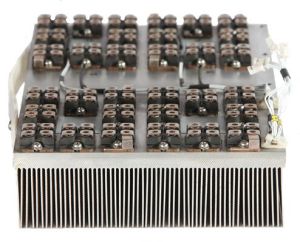
power module
The high power density and efficiency of the Power Modules of DSA series Power Amplifier is the heart of the system. These modules can use MOSFETs or IGBTs as their primary switching devices and can be coupled with numerous types of loads varying from resistive to inductive. As they are designed in a Class-D Full Bridge configuration, their operation is very similar to that of a buck converter. At output voltages lower than the input voltage, output current can be higher than the input current, as long as the input power is equal to the sum of output power and losses. Every power module is rack mounted and features a wire free design implemented using copper bus bars instead of wires. This ensures that our power module never faces any issues pertaining to loose or damaged connection. Each power module of the DSA series has a built-in PWM generation and management. These modules are stacked in master slave configuration for their parallel operation in the amplifier. PWM in paralleled modules is synchronised through master clock and a current feedback network is also implemented for precise current sharing amongst modules. Three-sigma design ensures peak current capability for continuous random operation, without affecting the life of the power device. Major Sub Systems of the Power Module are: Driver Section Driver section of the Power Module provides the necessary gate pulse to switch the conduction state of power devices from on to off and vice versa. A galvanic isolation-based gate driver circuit provides gate signals with negligible propagation and time delays. The final stage of the driver has a totem pole circuit in push-pull configuration for fast charging and discharging of the gate capacitances of the power devices at high frequencies. In a multiple module system, one module is master and the rest are slaves. The driver section of the master module generates the clock that is followed by every module in that system. This syncs all the PWM signals and reduces the final output ripple. The driver section also has two feedback networks. First is a voltage feedback to ensure output waveform is proportional to input waveform. Second is a current feedback to ensure equal current is drawn from every module in a system. Power Section We are connected in full bridge configuration and mounted on a common heat sink. The integral cooling fans ensure safe thermal operation. Each half of the bridge switches at modulated frequency such that the duty cycle varies at input signal rate. Each side is driven out of phase so that an amplified PWM signal appears across the bridge output. An array of heat sensors and two dedicated current sensors ensure the safety of this section. They are factory set to respond to the absolute maximum limits of the devices to ensure their safety in the event of a malfunction. Feedback Section Voltage feedback from the output terminal of the power section (within the output filter) to the PWM controller makes a flat response Power Amplifier. The loop incorporates DC and high frequency derivative feedback. An integrator in the loop provides linear gain and low harmonic distortion. Overall current of the power module is sensed by a non-contacting sensor which is used for the purpose of tripping and current sharing. Filter Section Sufficient attenuation to high frequency is done by LC filters to get a pure amplified output. The major part is a combination of inductor and low ESR high frequency capacitors. The final stage of the filter section contains capacitor network for minimising any noise and electromagnetic interferences along with the zobel network for impedance matching.
...more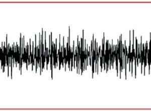
LTH control application
LTH control application recreates field recorded data on the shaker. Unlike TTH, LTH can reproduce vibration on the shaker same as road vibration. Recorded data can be an earthquake or bumps on a road. Uses: Reproduction of recorded data form field on laboratory shaker system Door slam testing can be conducted with LTH control application
...more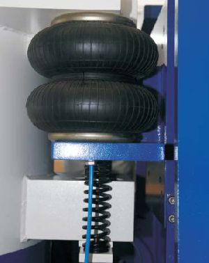
Isolation System
Our shakers are capable of producing vibrations over a wide range of frequencies at high g levels. These vibrations are produced on the armature head from where they are transmitted to various attachments and fixtures depending on the test. However undesirable it may be, a certain part of these vibrations are also transferred into the body of the shaker. It is necessary to isolate these vibrations in the body of the shaker from its base. This is achieved with a complex array of air bellows and spring placed between the shaker and its base. For further isolation, air bellows are attached to the bottom of the base or the combo base in case of a system with a Horizontal Slip Table. As a result, all system supplied by Sdyn can be installed in a multistory building as their is negligible dynamic weight due to vibration in the shaker body.
...more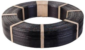
Field Structure
The magnetic circuit design of Sdyn’s Electrodynamic Shaker uses two field coils. Housed inside the shaker’s body, the field coils are always stationary and produce a constant flux which magnetises the iron, creating the two poles in front and back of the armature coil. When AC power flows through the armature coil, interaction of its flux with the magnetic lines flowing between the two poles causes the armature to move. Copper rings are placed directly in the front and at the back of the armature coil with minimal space to cancel the eddy current. The field coil is the primary source of heating inside the shaker as it is powered with a constant DC supply regardless of the test profile. In an air cooled system, these solid conductor coils are cooled by forced air which flows through the air gaps between the coils. In a water cooled system, these hollow conductor coils are cooled by water flowing inside the coils. To ensure proper cooling of the field coils in a water cooled system, both the field coils are built by stacking multiple disks of thin coils. These discs are connected in parallel for cooling and in series for power.
...more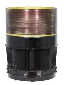
electrodynamic shaker
Sdyn’s SEV and SEW series of Electrodynamic Shaker produces vibration based on the principle of magnetism. The SEV series is air cooled and SEW series is water cooled, respectively. The product portfolio covers all ranges of shaker, from 10 kgf up to 32000 kgf and beyond. An Electrodynamic Shaker has two separate coils, one is stationary and the other is dynamic. A stationary coil or Field Coil helps in magnetising the iron to produce magnetic field lines and current flowing in the dynamic coil or Armature Coil interacts with these magnetic field lines to produce motion. This principle of magnetism is based on Maxwell’s Right Hand Rule and Fleming’s Left Hand Rule. Major Sub Systems of the Electrodynamic Shaker are: Armature Structure Our armature features a web structure to minimise weight, while maintaining structural integrity. The pattern can only be casted, therefore, in order to achieve the best quality, we import these castings from one of the world’s most renowned sources. Complete tooling, milling, drilling, and tapping of these castings is performed in our in-house CNC centre. The winding process is carried out at our headquarters in Roorkee, India. Special epoxy is used to ensure that the coils adhere to each other as well as the armature structure. Air cooled systems use a solid conductor and water cooled systems use hollow conductor with very heavy insulation. For an air cooled system, power is transferred to the armature coil using highly flexible copper ropes. For a water cooled system, power and water are transferred on the same line using highly flexible copper ropes and hose pipes, respectively. Only oxygen free copper is used to ensure long life of the conductor.
...more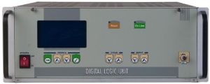
Digital Logic Unit
The microcontroller based Digital Logic Unit (DLU) controls and monitors the system features and safety interlocks of the DSA series Power Amplifier. The logic unit acts as a user friendly interface between the user and the equipment and can be operated both in manual and auto modes. System parameters and trip interlocks are displayed on the alphanumeric display of the feather touch membrane keyboard front panel. Soft start and controlled shut down is offered with an online key on the front panel. Shaker and amplifier safety interlocks are monitored and indicated on the front panel through a microcontroller chip. Interlock signals are routed through isolators and buffer network for proper latching and to prevent false triggering. The signals are latched on to the fault analysis section of the microcontroller. Only after all faults are resolved, the system is allowed to go Online and increase the gain. Major system interlocks associated with DSA series of amplifier are over current, field fail, displacement limit, cooling shaker, over temperature, etc. Major Sub Systems of the Digital Logic Unit are: Internal Oscillator The internal oscillator is a feature provided in the DLU for manual mode of operations wherein the g level is not controlled. The output of the internal oscillator is a pure sine wave. Its gain is controlled via the feather touch membrane keyboard front panel. Output voltage, current and frequency are displayed on the alphanumeric display. The oscillator is capable of producing sine wave from 1Hz to 10kHz. Signal Source Selection As the DLU can generate its own sine signal in addition to the external signal from a Vibration Controller, it features a signal source selection that allows users to seamlessly switch between internal and external signal source using the feather touch membrane keyboard front panel. The selectable signal path offers negligible resistance and ensures signal integrity. Gain Control The highly integrated gain control block of the DLU is designed using a digital potentiometer. All changes in gain are made gradually, one step at a time, to prevent any spike or sudden movement of the armature. Clamp and release operation is done automatically by the microcontroller inside the DLU based upon various inputs from the user and the interlocks. Auto Centring All shakers from Sdyn have dynamic auto centring. Models SEV 125 to SEV 180 feature mechanical auto centring. Models SEV 240 to SEV 760 feature a combination of mechanical and electronic auto centring. The mechanical auto centring is based on rubber bushes and cam bolt assemblies, which exhibit mechanical stiffness when the armature is at its centre. The electronic auto centring is based on optical sensors that centre the armature by filling or releasing air from a cup below the armature structure. For long stroke systems which require displacement of more than 51mm or 2 inch, a highly sophisticated laser based auto centring is provided. The suspension system of a long stroke system is different and offers no stiffness whatsoever. Therefore, this auto centring system controls pneumatics and DC output from the amplifier, in order to ensure the system achieves its centre with varied test loads.
...more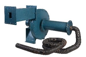
Cooling System
bellows and spring placed between the shaker and its base. For further isolation, air bellows are attached to the bottom of the base or the combo base in case of a system with a Horizontal Slip Table. As a result, all system supplied by Sdyn can be installed in a multistory building as their is negligible dynamic weight due to vibration in the shaker body. Cooling System It is not possible to run a shaker reliably without proper cooling because the extensive heat produced inside the shaker can damage the armature coil. Small shakers (50kgf and below) generally feature a permanent magnet instead of a field coil, therefore, they can operate without any cooling at light loads. A similar feature can also be offered with bigger systems to meet certain test requirements like Squeak and Rattle test being performed on an air cooled shaker. A shaker can either be air cooled or water cooled. Each method has its own key features, advantages, and disadvantages. Selecting a cooling method that meets customer’s test requirement is crucial. Both these methods are breitling replica discussed below: Air Cooling Method An air cooled shaker features a centrifugal blower for forced air cooling. A hose pipe connects the bottom of the shaker to the blower which sucks air from a perforated sheet at the top of the shaker. It is very important to ensure that the blower is not located in close vicinity of the shaker because this might cause the exhaust air from the blower to be sucked back by the shaker. In this scenario, the shaker’s temperature will keep increasing as it is being cooled by the same air in a loop, causing thermal runaway and even burning of the armature coil. To ensure safety and proper operation of the cooling system, various sensors are installed in the shaker that are mentioned below: mentioned below: Air Pressure Sensor – To ensure sufficient air pressure for proper suction Air Temperature Sensor – To stop the system if the air temperature is too high to ensure proper cooling Due to suction, audible noise is always present near the shaker and the blower. It is suggested to take measures during installation to prevent this audible noise from creating an un-conducive working environment for the test/ lab personnel. Water Cooling Method A water cooled shaker features a dedicated cooling system for storing, circulating, and cooling distilled water that is used for cooling. The system is assembled in two 19-inch racks of 42 unit height. Pressure pump is installed in the cooling rack to circulate distilled water at high pressure through the shaker’s field and armature coils. Heat exchanger is installed in the cooling rack to cool this distilled water with another supply of water from a cooling tower or chiller at the customer’s site. To ensure safety and proper operation of the cooling system, various sensors are installed in the cooling racks that are mentioned below: Liquid Pressure Sensor – To measure the water pressure in the pipes in order to detect any obstruction in the pipeline Liquid Flow Sensor – To measure the water flow in the pipes in order to detect any leakages in the pipeline Liquid Temperature Sensor – To measure the temperature of the incoming and outgoing water in order to detect overheating
...more
Classical Shock Control Application
Drop test methods do not provide accuracy and repeatability like Classical Shock testing. This tests determines if the UUT can withstand transient vibrations encountered during its life in real environmental conditions.. Uses: Computation of shock response spectrum Bump/ Impact test replacement by shaker
...more
Power Amplifier
Sdyn’s Power Amplifiers use compact and extremely efficient power modules. These help to amplify the small electrical signal from the Vibration Controller to a proportionally high voltage and high current output, that is ideal to drive the shaker. The design of the Power Amplifier ensures energy and space. DSA series Power Amplifier use solid-state power devices in a Class-D Full Bridge configuration. They are digitally modulated with a high frequency pulse width modulated signal with efficiency of over 92%. Their modular construction makes them easy to handle and arrange for maximum output power with direct coupling to any resistive or inductive load. Integral air cooled design ensures continuous duty cycle without sacrificing performance at peak temperature and humidity. These Power Amplifiers are compatible with any make of Electrodynamic Shakers and are designed to provide continuous rated voltage and current at high ambient temperature and humidity. A low knee filter provides smooth output, while removing switching noise and electromagnetic interference. A zobel network is dedicated for impedance matching over a wide range of frequencies for inductive loads. Adjustable current limit is also provided for controlling maximum output power so that accidents can be avoided. Assembled in industry standard modular racks, all modules of our Power Amplifier are rack mountable. Removing and installing modules is made easy via guide rails on which every module is designed to slide. Designed to meet international design and safety standards, every module of our Power Amplifier is feature rich and contains its own power entry, power filtering, error indication and EMI conforming systems. Continuous upgrade of technology to better meet the international standards and reduce the carbon footprint of our system is a never-ending process at Sdyn. Through our various training, services and maintenance programs, we keep our customers updated with the latest product offerings and upgrades. Major Sub Systems of the Power Amplifier are:
...more
Power Amplifier Remote
Power Amplifier Remote is provided as a separate module for applications that require remote control of the Power Amplifier and monitoring of all parameters and interlocks on a PC. This feature completely replicates the functionality of the LCD screen and the feather touch membrane keyboard on the Power Amplifier on the PC. It provides customers with the capability to control and monitor the following: System Controls Shaker Field Shaker Cooling Reset Online Amplifier Gain System Parameters Output Voltage Output Current Amplifier Temperature Shaker Temperature Gain
...more
HVDC Section
The Power Amplifiers run on a widely acceptable range of 3-phase mains input and does not require any special operating environment or support equipment. Step-down 3-phase AC output of highly efficient vacuum impregnated transformer is rectified using three phase bridge rectifiers. Bridge rectifiers of single body construction are used for space saving and good heat sinking characteristics, alongside high voltage capacitors to suppress transients and minimise mains ripple. Different protection circuits are coupled at various stages for synchronisation. Single Phase Preventer is used at the 3-phase input, which senses any phase replica watches loss and any imbalance in 3-phase line voltage through phase synchronisation relay. It also displays the phase status on the Digital Logic Unit.
...more
Electrodynamic Vibration Systems
Sdyn’s Low Thrust Series of Electrodynamic Vibration Systems comprises of our air cooled shakers and air cooled amplifiers. These are designed for low payload capacity and for tests that require high resonance and frequency response. A customer chooses this range for its low price, small form factor, and high reliability. These systems are generally very specific to the customer’s testing requirements and offer very little scope for future up-gradation. Standard features of Low Thrust Series are: Electromagnetic Armature and Field Coils Magnesium Alloy Casting based Armature Structure Dual Field Coil based Magnetic Circuit Class D Full Bridge (H Bridge) Power Amplifier Advanced features of Low Thrust Series are: Explosion Proof Design Remote Operation from PC Modified Shaker and Controller for Damper Testing using Force and Acceleration Sensing Modified Shaker and Controller for Rubber and Elastomer Testing using LVDT and Load Cell Some common applications of Low Thrust Series are: Testing to meet BIS Test Specifications Electronics and Electrical Component Testing LED and Bulb Testing Sensor and Transducer Testing Transmission Line Damper Testing Rubber and Elastomer Testing Ranges covered under Low Thrust Series are: SEV 125 (100 to 150 kgf) SEV 140 (200 to 300 kgf) SEV 180 (400 to 600 kgf) SEV 240 (1000 to 1500 kgf)
...more
Medium Thrust Series
Sdyn’s Medium Thrust Series of Electrodynamic Vibration Systems comprises of our air cooled shakers and air cooled amplifiers. These are designed to address a wide range of test objects and attachments which represent generalised testing requirements. A customer chooses this range for its “value for money”, high scalability and high reliability. Being the most commonly opted range, these systems are used where a variety of tests are conducted on a single system. With features like body isolation and trunnion being standard, this series is the first pick of every national and international testing laboratory. Standard features of Medium Thrust Series are: Electromagnetic Armature and Field Coils Magnesium Alloy Casting based Armature Structure Dual Field Coil based Magnetic Circuit Class D Full Bridge (H Bridge) Power Amplifier Advanced features of Medium Thrust Series are: Long stroke design with displacement up to 76 mm (3 inch) Explosion Proof Design Remote Operation from PC Some common applications of Medium Thrust Series are: Automotive parts and assemblies Locomotive parts and assemblies Aeronautic parts and assemblies Industrial parts and assemblies Ranges covered under Medium Thrust Series are: SEV 300 (2000 to 2500 kgf) SEV 360 (3000 to 3500 kgf) SEV 440 (4000 to 6000 kgf)
...more
High Thrust Series
Sdyn’s High Thrust Series of Electrodynamic Vibration Systems comprises of our water cooled shakers and air cooled amplifiers. These are designed for large and heavy specimens of irregular shapes and sizes. A customer chooses this range for its sheer power, very high payload capacity, and high reliability. Being a part of big projects, everything about these systems is as per the customer’s requirement. Standard features of High Thrust Series are: Electromagnetic Armature and Field Coils Magnesium Alloy Casting based Armature Structure Dual Field Coil based Magnetic Circuit Class D Full Bridge (H Bridge) Power Amplifier Advanced features of High Thrust Series are: Explosion Proof Design Remote Operation from PC Some common applications of High Thrust Series are: Aeronautics and Astronautics Arms and Ammunitions Ranges covered under High Thrust Series are: SEW 500 (7000 to 10000 kgf) SEW 590 (13000 to 16000 kgf) SEW 760 (29000 to 32000 kgf
...more
Horizontal Slip Table
The axis of a shaker’s operation is Z axis. In order to achieve vibrations in X and Y axis, a Horizontal Slip Table (HST) is used. A Horizontal Slip Table is compactly constructed using a precisely machined magnesium alloy tool-plate, which rests on top of the flat granite block. Hydraulic bearings are placed at different locations based on the design of the HST to constrain its motion in the same axis as that of the shaker. A consistent oil film is generated on the granite block and in the bearing in order to remove friction, provide dynamic support, control crosstalk and restrain overturning moments. The hydraulic bearings can be low or high pressure type depending on the table specification. High pressure bearings have a lower clearance and require higher pressure to operate as compared to low pressure bearings. Driven by our bull nose design based drive bar, the Horizontal Slip Tables provide excellent performance for heavy, tall or eccentric loads. The test object can be rotated by 90° on the table to switch between X and Y axis. A system integrated with HST is capable of testing objects in all three axis, one at a time. Major Sub Systems of the Horizontal Slip Table are:
...more
Trunnion Assembly
An optimised gear based pivoting system to turn the shaker from its ideal vertical position to a horizontal position using mechanical or electrical means. Locking bolts are provided on either sides to lock the trunnion assembly at the point where the shaker is precisely aligned vertically for operating on Armature or horizontally for operating on Horizontal Slip Table. A mercury switch is used to detect the orientation of the shaker by the Power Amplifier to enable or disable relevant interlocks automatically.
...more
Head Expander
The diameter of the shaker’s armature is limited by the rating and design of the shaker. Many times, the dimensions of the test object exceeds the working area offered by an armature. In order to increase the working area of an armature, a head expander is used. We offer a varied range of head expanders to meet various testing requirement like accommodating large test articles or multiple test objects at one time. They are manufactured by welding magnesium alloy tool plates which are also used in making the coupling for Shaker to HST. They are available for any size armature with customised hole pattern as per customer requirement. Sdyn manufactures the following types of Head Expanders: Circular Head Expander The top of the expander is circular. Any hole pattern can be provided as per customer requirement. Response is better than Square Head Expander as there are no sharp corners but the usable working area is less. Square Head Expander The top of the expander is square. Any hole pattern can be provided as per customer requirement. Due to the four sharp corners of the square shape, the response is not as good as in the case of a Circular Head Expander but the usable working area is more. Square Head Expanders are manufactured on order basis as per customer requirement.
...more
Vertical Load Support
Some test objects are not uniform and require eccentric or overhanging loading. In X and Y axis, the Horizontal Slip Table constraints the Armature of the shaker in one direction using bearings, but in Z axis, the same is not true for the Head Expander. A Head Expander is not supported by the shaker and there is a limit to how much working area you can increase using it for a given Armature size. For these non-uniform test objects, a Vertical Load Support (VLS) is provided which is a guided Head Expander. This attachment is supported by linear or hydrostatic bearings attached to the body of the shaker. The bearings constrain the motion of the VLS to Z axis only. Air bellows are provided for further support, if required. A Vertical Load Support can be designed in a square or rectangular shape based on the customer requirement.
...moreBe first to Rate
Rate ThisOpening Hours