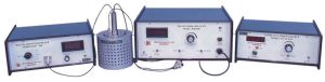
Two Probe Setup
We Offer Two Probe Method, It is One of the Standard and Most Commonly Used Method for the Measurement of Resistivity of Very High Resistivity Samples like Sheets/films of Polymers. the Resistivity Measurement of such Samples is Beyond the Range of Four Probe Method. the Experimental Set-up Consists of the Following: 1. Two Probes Arrangement, Tpa-01 it Has Two Spring Load Contact Probes. These Probes Move in a Pipe and are Insulated By Teflon Washers. this Probes Arrangement is Mounted in Suitable Stand, Which also Hold the Sample Plate and Rtd Sensor. the Stand also Serves as the Lid of Pid Controlled Oven. Teflon Coated Leads are Provide for Connecting with High Voltage Power Supply Eht-11 and Digital Picoammeter Dpm-111. with the Set-up Assuming Max. Voltage = 1500v; Current 100x10(-12) a (max) and Thickness of Sample 1mm. the Resistivity of the Sample Could Be Measured upto 1014 Ohm.cm. 2. Pid Controlled Oven, Pid-200 this is a High Quality Temperature Controlled Oven Suitable for Four Probe Set-up. the Oven Has Been Designed for Fast Heating and Cooling Rates, Which Enhances the Effectiveness of the Controller. While the Basic Design of the Controller is Around the Pid Configuration for Its Obvious Advantages, Wastage of Power is Avoided By Using a Pulse Width Modulated (pmw) Switch. this Combination Has the Advantages of Both On-off Controller and Linear Pid Controller. the Result is a Good Stable and Accurate Temperature Control. platinum Rtd Has Been Used for Sensing the Temperature. a Wheatstone Bridge and An Instrumentation Amplifier are Used for Signal Conditioning. Feedback Circuit Ensures Offset and Linearity Trimming to a Great Degree of Accuracy. the Set and Measured Temperature are Displayed On 3â½ Digit Dpm Through Selector Switch. specifications of the Oven temperature Range: Ambient to 200c resolution: 0.1c short Range Stability: +-0.2c long Range Stability: +-0.5c measurement Accuracy: +-0.5c (typical) oven: Specially Designed for Two Probe Set-up sensor: Rtd (a Class) display: 3.5 Digit, 7 Segment Led power: 150w 3. High Voltage Power Supply, Eht-11 output: 0-1500v Continuously Adjustable current: 1ma (max.) polarity: +ve or -ve, as Required regulation: +-0.05% for 0 to 1ma Load stabilization: +-0.02% for +-10% Mains Variation display: 3.5 Digit, 7 Segment Led Dpm connection: Output Through a Amphenol Connector On the Front Panel protection: Fully Protected Against Overload and Short Circuit By Current Limiting Technique power Requirements: 220v +-10%, 50hz weight: 5kg dimensions: 240mm X 390mm X 130mm. 4. Digital Picoammeter, Dpm-111 multiplier: X1, X10, X10(2), X10(3), X10(4), X10(5) accuracy: 0.2% for all Ranges resolution: 1pa, 10pa, 100pa, 1na, 10na, 100na input Resistance: 2.5k Ohm, 0.25k Ohm, 25 Ohm, 2.5 Ohm, 0.25 Ohm, 0.025 Ohm display: 3.5 Digit, 7 Segment Led (12.5mm Height) with Auto Polarity and Decimal Indication. input: Through Amphenol Connector. power Supply: 220v +-10%, 50hz. weight: 2.5kg. dimensions: 240mm X 275mm X 120mm. the Experimental Set-up is Complete in all Respect.
...more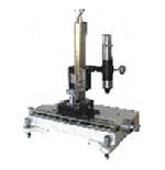
Travelling Microscope, TVM-03
We offer Travelling Microscope in this, the bed is of a heavy casting, thoroughly aged and machined, is fitted with leveling screws. On the dovetail guide ways slides the horizontal carriage which can be clamped at any positioon by means of a thumbscrew. A second sliding carriage slides along a gunmetal vertical pillar fitted on the horizontal carriage. The slow motion guide bars are made of sturdy material and the motion is very smooth. Microscope tube inclinable in any angle. true vertical and horizontal positions marked focusing. Scales and Verniers Made of lifetime Stainless Steel. Optics (i) True achromatic objective with 7.5 cm, focusing distance from object. (ii) 10X Ramsden Eyepiece with fine cross wire. Scale and Vernier (i) Horizontal scale: 180 mm with a screw gauge type motion (ii) Vertical scale: 150mm with a vernier scale (iii) Lateral Scale: 60mm with a vernier scale (iv) Least Count: 0.01mm on all scales
...more
Travelling Microscope
We offer Travelling Microscope in this, the bed is of a heavy casting, thoroughly aged and machined, is fitted with leveling screws. On the dovetail guide ways slides the horizontal carriage which can be clamped at any positioon by means of a thumbscrew. A second sliding carriage slides along a gunmetal vertical pillar fitted on the horizontal carriage. The slow motion guide bars are made of sturdy material and the motion is very smooth. Microscope Tube Inclinable in any angle. true vertical and horizontal positions marked focusing. Scales and Verniers Made of lifetme Stainless Steel. Optics (i) True achromatic objective with 7.5 cm, focusing distance from object. (ii) 10X Ramsden Eyepiece with fine cross wire. Sclae and Vernier (i) Horizontal scale: 18 cm divided at 1mm interval (ii) Vertical scale: 16cm divided at 1mm interval (iii) Screw gauge dial: 100 divisions with a least count of 0.01mm
...more
Travelling Microscope
1 Piece (MOQ)
Color : Grey
Condition : New

temperature control system.
1 Set (MOQ)
Application : Control Lab Trainer
Model Number : TCS-02
Display Type : Digital
Color : Grey
Brand Name : Techno
...more
Study of Thermoluminescence of F-centers Experimental setup
We offer Thermoluminescence of F-centres, in this Pure alkali halide crystals are transparent throughout the visible region of the spectrum. The crystals may be colored in a number of ways (1) by the introduction of chemical impurities (2) by introducing an excess of the metal ion (3) by X-ray, γ-ray, neutron and electron bombardment (4) by electrolysis Colour centres produced by irradiation with X-rays When a X-ray quantum passes through an ionic crystal, it will usually give rise to a fast photo-electron with an energy of the same order as that of the incident quantum. Such electrons, because of their small mass, do not have sufficient momentum to displace ions and therefore loose their energy in producing free electrons, holes, excitons and phonons. Evidently these while moving near the vacancies form trapped electrons as well as trapped holes. The trapped-electron or trapped-hole centres so formed can be destroyed (bleached) by illuminating the crystal with light of the appropriate wavelength or warming it. The experiment consists of the following Experimental set-up for creating thermoluminescence (1) Sample: KBr or KCl single crystal (2) Thermolumniscence Temperature Meter, TL-02 Digital Thermometer Oven Power Supply (3) Sample Holder (4) Thermoluniscence Oven (0-423K) (5) Black Box For measurement of luminescence intensity (1) Photomultiplier tube: 931A (2) PMT Housing with biasing circuit and coaxial cables etc. (3) High Voltage Power Supply, Model: EHT-11 Output : 0-1500V variable (1mA max.) Regulation : 0.05% Display: 3.5 digit 7-segment LED (4) Nanoammeter, Model DNM-121 Range: 100nA to 100mA full scale in 4 ranges Accuracy : 0.2%. Display: 3.5 digit 7-segment LED Complete in all respect, only X-ray facilities are required to create F-centers in the crystal.
...more
Study of Temperature Transducers
We offer Study of Temperature Transducers, STT-01usefull for control labs. Measurement of temperature is an important task in a large number of physical processes. A transducer in a device which converts the temperature information into an electrical signal usually voltage, for an automated processing. A very wide variety of temperature transducers are commonly available which differ from each other with regards to there: (a) Range of operation (b) Sensitivity and linearity (c) Accuracy, Stability and Repeatability (d) Speed of response The present experiments has been designed to study the input-output characteristics of some common transducers like, thermistors (PTC and NTC), thermocouple, semiconductor sensors and may be extended to also study the temperature coefficients of resistance. Highlights >>Temperature controlled oven with digital display >>Instrumentation amplifier with gain switching >>Digital voltmeter >>Interfacing circuits for common transducers Experiments >>Temperature-output voltage characteristics of the following transducers in the temperature range of room temperature to 150°C and determination of their parameters Thermocouple - Chromel - Alumel - Copper - Constantan (optional) Thermistors - NTC - PTC Semiconductor sensor (type AD590) upto 90C only Features and Specifications:- >>Temperature controlled oven upto 150C with digital temperature display >>Digital voltmeter on the panel for sensor output measurement >>Built-in interfacing circuit and switched gain instrumentation amplifier >>IC regulated power supplies and detailed manual The experiment is complete in all respect.
...more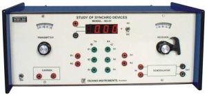
Study of Synchro Devices
We offer Study of Synchro Devices useful for control labs. Highlights >>Synchro transmitter-receiver pair with calibrated dials >>Locking system for receiver rotor >>Receiver use as control transformer >>Built-in balanced demodulator circuit >>Panel meter for ac/dc voltages >>All internal power from the 220 V/50 Hz mains >>Only an external CRO required Introduction >>Basic characteristics study - stator voltages as a function of the rotor angle using the built-in ac voltmeter. This shows the space variation of the three voltages, VS1S2, VS2S3, and VS3S1, causing rotation of the resultant magnetization in the stator which is fundamental to the error detection process. >>Operation and error study of the transmitter-receiver pair as a simple open loop position control at a very low torque. This is a rarely used application but is used to demonstrate the direction of the resultant magnetic field in the receiver. >>Plotting the error voltage output as a function of the transmitter rotor angle with the receiver rotor locked. Observing the 180° phase reversal around the zero error is significant as this the basic method through which the direction of the error is detected in an ac system >>Use of balanced demodulator to develop dc error signal with appropriate polarity and compare it with the ac error. This block would be needed if a mixed system were to be designed using both dc and ac components. The experiment is complete in all respect except a CRO.
...more
Study of Stepper Motor
We offer Study of Stepper Motor useful for control labs. This experimental set-up aims at providing an exposure to the basic operation of a stepper motor, its drive and logic, and limitations as far as the internal dynamics is concerned. Experiments have been designed to demonstrate the effect of external load inertial and frictional, on the motor performance. Provisions are available for free running operation as well as single stepping mode with LED indication for the active phase. The unit may also be operated by a microprocessor kit for which a built-in interfacing and automatic changeover has been provided. It may be seen that this is a complete experiment set and not a microprocessor kit with an ADD-ON card and a motor. Highlights >>Stepper motor operation through pulse circuit >>Stepper motor operation through 8085 mp kit >>Built-in programs in EPROM >>Dynamic response study Experiments >>Manual stepping through push button switch. Measurement of step angle. >>Speed and direction control logic by recording the pulse sequence. >>Study of resonance effect at various speeds >>Display and measurement of the dynamic characteristics of the motor in the wobble mode. >>Calculation of 'single stepping' and 'slew' regions. >>Programming the microprocessor kit to implement features like direction, speed, angle of rotation, number of steps or an arbitrary motion >>Study of the effect of inertial and frictional loading on the dynamic performance Features and Specifications >>Single stepping and free running modes of operation with speed variation and direction reversal - internal TTL circuit. >>360 degree motion Servo-Potentiometer position -pickup for motor dynamics >>Operation through microprocessor kit sample control programs provided >>Stepper motor specification Torque: 2.8 Kg-cm Step angle: 1.8 degree Power: 12V, 1A/phase >>Essential accessory - a CRO The experiment is complete in all respect except - a CRO.
...more
Study of Second Order Networks
We offer Study of Second Order Networks useful for control labs. Second order networks are important because of the fact that these are the simplest networks that produce the complete range of transient response – from over damping to near oscillations. Although theoretical discussions are normally confined to passive RLC networks, such networks are limited in their performance due to the rather large resistance of any reasonable value inductance that might be constructed to operate at frequencies of few kHz. In the present unit active RC-network has been designed which span the complete behavior of an equivalent passive RLC network. The user thus has the experience of studying a near ideal passive second order network complete with all theoretical computations and their experimental verifications. Highlights >>Active second order network >>Damping control–over-, critical-, and under-damping >>Built-in sine wave signal >>Needs an external CRO for response study >>Operates with 220V/50 Hz >>Detailed technical literature and experiment results supplied Experiments >>Observe and trace from the CRO screen the step response for different values of zeta. >>Compute approximate values of equivalent network parameters. >>Plot the frequency response for various of zeta and observe resonance Features and Specifications >>Active RLC network using 3-Op Amps >>Damping 1.1-0.1 (approx) >>Square Wave 35-700 Hz., 0-1V (typical) >>Sine Wave 35-700 Hz., 0-1V (typical) >>Essential accessory: a CRO The experiment is complete in all respect, except a CRO.
...more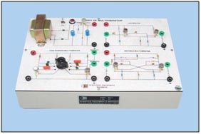
Study of Multivibrators
We offer Study of Multivibrators, this experiment consists of the following: >>Free Running vibrator >>Univibrator >>Bistable Multivibrators >>Regulated Power Supply The free running multivibrator also serve as a pulse generator for the study of bistable multivibrator and univibrator. The set-up is so designed that no high voltage is exposed and hence safe in handling by the students.
...more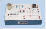
Study of Modulation and Demodulaion with Built-in Carrier Frequency Source (Solid State)
We offer Study of a Modulation and Demodulation with Built-in Carrier Frequency Source (Solid State), the following studies can be carried out with this set-up: Carrier signal testing. Variation of modulated wave with the modulation signal. Study of detector circuit. The experimental set-up is provided with a built-in power supply. Accessories Required: (i) Function Generator, FG-01 (ii) Oscilloscope The set-up is so designed that no high voltage is exposed and hence safe in handling by the students.
...more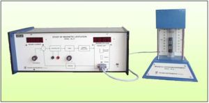
Study of Magnetic Levitation System
We offer Study of Magnetic Levitation System useful for control labs. Magnetic Levitation, lifting of objects under the influence of a magnetic field, has numerous application including some advance locomotives designed on the repulsive force of a magnet. The present unit, based on the attractive force of an electromagnet, is inherently unstable. There is no way to keep an iron object suspended in air by manually adjusting the current in the electromagnet. Even a feedback control with forward path gain control alone is ineffective. These facts are brought out by studying and experimenting with the dynamics of the system. The next task consists of the design of suitable controller and implementing the same to achieve the desired objective. A sound knowledge of MATLAB and its availability should be highly desirable, though not essential, for the conduct of this experiment. The basic theory, analysis and sample calculation are described in the accompanying literature. Highlights >>Object suspended in air by magnetic force excellent visual impact >>Controller design to maintain stability >>Up-down position setting by reference control Experiments >>To develop the transfer function of the system through laboratory >>To design/implement PD and lead compensation with different parameter >>To simulate the system in MATLAB and study in detail various control option and their response Features and Specifications >>Object suspended in air by magnetic force >>Controller design to maintain stability >>Position changing by reference >>Built-in power supplies, meters etc >>220V/50Hz operation >>Detailed technical literature included The experiment is complete in all respect.
...more
Study of Hybrid Parameters of a Transistor Experimental Setup
We offer Study of Hybrid Parameters of A Transistor,the following studies can be carried out with this set-up: Study of h(11) parameter (input impendance parameter). Study of h(22) parameter (output admittance parameter). Study of h(21) parameter (forward current transfer ratio). Study of h(12) parameter (reverse voltage feedback ratio). The experimental set-up is provided with a built-in power supplied and is complete. The set-up is so designed that no high voltage is exposed and hence safe in handling by the students.
Country of Origin : India
Size : 13x13x7
...more
Study of Digital-to-Analog Converter
We offer Study of Digital-to-Analog Converter, DTA-01 useful for control labs. Measurement of the speed of a rotating shaft is a common requirement in many industrial and laboratory applications. Stroboscope, is a convenient-to-use, direct reading speed measuring instrument. A highly stable function generator IC based circuit provides the basic variable frequency timing pulses. These are read on an IC based LCDLED counters with direct speed display in rpm. The flasher unit generates the high intensity flashes at a suitably scaled rate directed towards the rotating shaft. Precision potentiometer's makes the task of speed setting very precise. The portable model, fitted into a light weight and strong plastic body is more suited for industrial class room environment. Highlights >>Basic 4-bit weighted resistance >>4-bit R-2R network module >>10-bit IC Type AD7533 with mechanical switches >>Microprocessor interfaced 10-bit converter Experiments >>Study of the circuit diagram and performance of a 4-bit weighted resistance type DA converter. The digital inputs are to be given by operating four mechanical switches. >>The above experiment is conducted on a 4-bit discrete component R-2R network based unit. >>Manual operation of a 10-bit IC DA converter type AD7533 through 10 mechanical switches. >>Operation of the IC based circuit through the microprocessor kit provided. Some typical waveform generation exercises are suggested and solutions are provided. More problems can be attempted by the student with help from his supervisor. Features and Specifications >>Advanced Experiments-arbitrary waveform generation >>Panel Meter for all measurements >>A measuring CRO is needed for viewing the waves forms The experiment is complete in all respect, except a CRO.
...more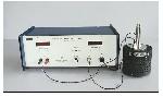
Study of Dielectric Constant
We offer Study of Dielectric Constant and Curie Temperature of Ferro electric Ceramics. Dielectric or electrical insulating material are understood as the material in which electrostatic field can persist for long times. Layers of such substance are commonly inserted into capacitors to improve their performance, and the term dielectric refers specifically to this application. The present setup demonstrates is useful for students to get first hand experience of this parameter in laboratory environment. Description of the experimental set-up 1. Probes Arrangement, DEA-01: It has two individually spring loaded probes. The probes arrangement is mounted in a suitable stand, which also holds the sample plate. 2. Sample Barium Titanate (BaTiO3) 3. Oven, DEO-01: This is a high quality temperature controlled oven. The oven has been designed for fast heating and cooling rates, which enhances the effectiveness of the controller. 4. Main Units: The Set-up consists of two units housed in the same cabinet. a) Oven Controller Platinum RTD (A class) has been used for sensing the temperature. A Wheatstone bridge and an instrumentation amplifier are used for signal conditioning. Specifications of the Oven: Temp. Range: Ambient to 200°C Resolution: 1°C Stability: ±0.2°C Accuracy: ±0.5 (typical) Sensor: RTD (A class) Display: 3½ digit, 7 segment LED with autopolarity and decimal indication Power: 150W b) Digital Capacitance Meter: This a compact direct reading instrument for the measurement of capacitance of the sample. Specifications Range: 50-6000pf Resolution: 1pf Display: 3½ digit, 7 segment LED with autopolarity and decimal indication.
...more
Study of Basic Operational Amplifier, Type- 741
We offer Study of Basic Operational Amplifier, TYPE-741, the following studies can be carried out: Working of the basic circuit. Measurement of bias and offset currents. Study of inverting and non-inverting configurations. Study of Amplier drift. The set-up is so designed that no high voltage is exposed and hence safe in handling by the students.
...more
Study of Astable & Monostable Multivibrator using Timer IC, Type- 555
We offer Study of Astable & Monostable Multivibrator using Timer Ic,TYPE-555, the following studies can be carried out with this setup: Operation as a free running multivibrator Operation as a monostable multivibrator Operations as a preset time delay. The set-up is so designed that no high voltage is exposed and hence safe in handling by the students.
...more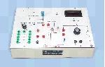
Study of an Integrated Circuit Regulator
We offer Study of Integrated Circuit Regulator, the following studies can be carried out: (i) Study of a voltage regulator. (ii) Study of a current regulator. The experimental set-up consists of an IC 723 with facilities for convenient connections, an unregulated power supply, voltmeter, an ammeter and all the other components required to perform the experiments. The set-up is so designed that no high voltage is exposed and hence safe in handling by the students.
...more
Study of a Transistor Amplifier (RC Coupled) Cum Feed-Back Amplifier
We offer Study of a Transistor Amplifier (Rc Coupled) Cum Feed-Back Amplifier with this following studies can be carried out with this set-up Study of the basic circuit of a RC Coupled Amplifier. Frequency response of RC Coupled Amplifier. Effect of negative feedback on the gain and frequency response of the amplifier Effect of positive feedback on the gain and frequency response of the amplifier. Verification of the condition of oscillation. Study of different classed of amplifier. Accessories Required (i) R.F. Oscillator (ii) True RMS A.C. Millivoltmeter, ACM-102 The set-up is so designed that no high voltage is exposed and hence safe in handling by the students.
...more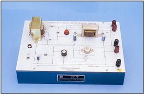
Study of a Solid State Power Supply
We offer Study of a Solid State Power Supply,following studies can be carried out with this set-up (1) Study of rectification. (a) Full wave rectification (b) Half wave rectification. (2) Study of ac component (Ripples): (a) Efficiency of various type of filters - ???, T type etc (b) The effect of load (c) The effect on regulation (3) Regulation characteristics: (a) The effect of load on regulation. (b) The effect of change in main’s voltage. Accessories Required : (i) Multimeter, (ii) Oscilloscope The set-up is so designed that no high voltage is exposed and hence safe in handling by the students.
...more
study of op amp 741 applications amplifier
We offer Study of 741 Applications, Features • Study of linear and non linear applications as: - Integrator - Differentiator - Summer - Subtractor - Voltage to Current converter - Current to Voltage converter - Astable Mode - Precision rectifier • Built-in power supply • Built-in square wave and triangular wave Generator • Built-in current source. The set-up is so designed that no high voltage is exposed and hence safe in handling by the students.
Country of Origin : India
Size : 850x550x1100 Mm
Type : Physics Instruments
...more
Stroboscope
We offer Stroboscope usefull for control labs. Measurement of the speed of a rotating shaft is a common requirement in many industrial and laboratory applications. Stroboscope, is a convenient-to-use, direct reading speed measuring instrument. A highly stable function generator IC based circuit provides the basic variable frequency timing pulses. These are read on an IC based LCD/LED counters with direct speed display in rpm. The flasher unit generates the high intensity flashes at a suitably scaled rate directed towards the rotating shaft. Precision potentiometer's makes the task of speed setting very precise. The portable model, fitted into a light weight and strong plastic body is more suited for industrial / class room environment. Operating instructions are included in the Instruction manual accompanying the unit. Highlights Non-contact speed measurement High intensity flashes Direct speed reading in RPM No shaft modification Features and Specifications Speed range: 500-9900 rpm Crystal Controlled accuracy Mains Operation Display: 4 digit LED Freq. control: 10 turn Potentiometer Study Desktop Model Suitable for class room environment The experiment is complete in all respect. Features >>Speed range : 500-9900 rpm >>Crystal Controlled accuracy >>Mains Operation >>Display : 4 digit LED >>Freq. control : 10 turn Potentiometer >>Sturdy Desktop Model >>Suitable for class room environment
...more
Semiconductor Diodes Characteristics
We offer Semiconductors Diodes Characteristics with this following characteristics can be studied: • Forward and reverse characteristics of Ge, Si diodes and LEDs • Study of Zener diode characteristics • CRO display of forward and reverse characteristics. The set-up is provided with a booklet which contains its theory of operation, description, suggestions and discussion of the experiments that my be performed with it. The circuit is all electronic using transformer and electronic components Viz. IC’s, transistors, capacitors and resistance etc. The whole circuit operates on 200V +-10% 50 Hz AC and mounted in a metallic cabinet which is grounded through the grounding lead of power connector and hence safe towards electrical hazard, if any.
...more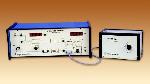
DC Speed Control System
We offer D.C. Speed Control system usefull in control laboratory experiment. The present unit, built around a small permanent magnet d.c. motor, is designed to bring out the salient features of such a system. Facilities are available to directly measure the principal performance features of the speed control system, viz., steady state error and load disturbance rejection, as a function of the forward path gain. In addition, the experimental work involves the determination of the motor transfer function and the characteristics of the tachogenerator. An important feature of the unit is the built-in absolute speed measurement through optical pick-up from a slotted disk followed by a frequency counter. Variable loading of the motor is achieved by a built-in eddy current brake. Highlights >>Closed loop motor speed control with eddy current brake >>Compact system-no mechanical hassles >>Opto electronic speed sensor >>Digital display of speed on the panel Experiments >>Effect of loading on the speed of the motor in the open loop >>Steady state error variation with forward gain >>System time constant variation with forward gain >>Effect of forward gain on disturbance rejection >>Determination of the motor transfer function and tachometer characteristics Features and Specifications >>Speed control of a 12V, 4W permanent magnet d.c. motor >>Speed range: 0 to 3000 rpm (typical) >>Opto-interrupter based speed sensing >>4-digit speed display in rpm >>Electronic tachogenerator for feedback >>Separate unit for motor in a see-through cabinet >>Smooth, non-contact eddy current brake for loading >>Built-in 3.5 digit DVM for signal measurements >>Built-in IC regulated internal power supply >>110V +-10%, 60Hz mains operation >>Supporting literature and patch cords included >>Essential accessory – a CRO The experiment is complete in all respect, except a CRO.
...more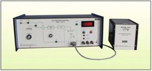
AC Position Control
We offer A.C. Position Control System usefull in control laboratory experiment. 2-phase ac servomotors have been traditionally used for position/ speed control applications especially in light weight, precision instrumentation area in airborne systems. The present unit is designed around a 12V ac servomotor and exposes the basic characteristics and dynamics of a position control system. A block diagram of the system is shown in figure below. Besides introducing the basic features like balanced modulation of the error signal, phase reversal around the set point and phase difference between the reference and control phases of the motor, the experiment involves study of the step response of the closed loop system. Being a mechanical system the response is too slow for a comfortable viewing on a CRO, except on an expensive storage oscilloscope. A microprocessor based waveform capture/ display card in the unit stores the step response in real time and displays the same once steady state is reached. Highlights >>2-phase A.C. Servomotor >>Servo Potentiometer for position sensing >>Transient response capture/display >>In-built rms voltmeter on panel Experiments >>Error detector characteristics, phase reversal >>Amplifier gain measurement >>Phase difference between control and reference windings >>Step response study Features and Specifications >>2-phase servomotor - 12 volt/phase, 50Hz, 10 watt >>Power amplifier for driving >>Servo potentiometer type error detector >>In-built 10.00 volt (rms) panel meter >>Step response capture/display card >>Detailed literature with typical results included >>Complete unit except a measuring CRO >>220 volts, 50 Hz mains operation The experiment is complete in all respect
...more
DC Position Control System
We offer D. C. Position Control System usefull in control laboratory experiment. This unit provides the students an opportunity to study and operate a practical electro-mechanical angular-position-control system. The system is built around a good quality permanent magnet armature controlled d.c. motor, speed reduction gear-set, potentiometric error detector using special 360 degree revolution servo potentiometers, a tachogenerator for velocity feedback and associated electronic circuits. The motor unit is housed in a separate cabinet with transparent panels for easy viewing. Interconnection with the main unit is through a standard 9-pin D-type connector. Experimental work on this system would enable the students to appreciate the difference in performance between idealized systems studied in the theory classes and the systems encountered in practice. Highlights >>Compact system - no mechanical hassles >>Simplified operation >>microprocessor based storage of response >>Positive/Negative tachogenerator feedback Experiments >>Operation of the position control system for different values of the forward gain to angular position commands >>Step response studies for various values of forward gain >>Study of the effect of velocity feedback on the transient and steady state performance of the system as well as its stability Features and Specifications: >>Position control of a 12V, 1A d.c. gear motor (50 rpm) >>Provision for positive and negative tachogenerator feedback >>Tacho constant: 2V/1000 rpm approximately >>Calibrated dials for reference and output position: resolution 1degree >>Servo-potentiometers with full 360 degree rotation >>microprocessor based waveform capture/display card >>Built-in 3.5 digit DVM for signal measurements >>Built-in step signal and IC regulated power supplies for electronic circuits >>Separate unit for motor in a see-through cabinet >>110V +-10%, 60Hz mains operation >>Literature and patch cords included >>Essential accessories - a CRO The experiment is complete in all respect, except a CRO.
...moreBe first to Rate
Rate ThisOpening Hours
Share your Correspondence Details to receive messages from Ses Instruments Pvt. Ltd.