
WIRLING OF SHAFT APPARATUS
The ‘J P T I’ unit consists of a base upon which bearing holders and driving motor is coupled. Bearing holder is provided for fitting various bearing to provide different conditions for test shafts, viz. both end fixed and one end free. A variac provided for speed control of driving motor. The unit demonstrates the phenomenon of whirling of shaft. After the test shaft cannot be used, hence unit only demonstrate the principle. One kinematic coupling and bearing for fixed or free ends without restraint. An electric motor: Universal, 5000 rev/min. frictional horse power. A dimmer stat for controlling speed of motor. RANGE OF EXPERIMENTS Display of the various models of whirls for a range of shafts with • Both end DIRECTIONALLY FREE. •One end FIXED and other FREE. Models of vibration can be studied and the frequency can be measured each case. SERVICE REQUIRED • Single Phase 15amp Electrical Connection. • Tachometer to measure the speed. • Suitable floor space area to mount the instrument.
...more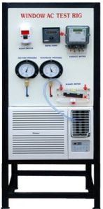
Window Air Conditioner Test Rig
The Window AC test rig is designed and manufactured such that the students can understand construction and working of a window type air conditioner and conduct the trial on it to evaluate performance of the same. The window AC is fixed in a rigid angle frame, with its cover cut half open to reveal the internal parts of the AC. The required pressure and temperature tapings are drawn for measurement of pressures and temperatures at salient points. Energy meter is provided for recording compressor energy consumption. A sling psychrometer is provided for measurement of inlet and outlet Dry-bulb & wet bulb temperature. With the help of manometer, velocity of air and consequently the flow rate of air can be determined. LIST OF EXPERIMENTS: • To determine Tonnage capacity of the Window type Air Conditioner by enthalpy difference method. • To determine actual C. O. P & theoretical C. O. P of the cycle. • To plot operating cycle on P-H chart.
...more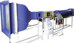
wind tunnel
SPECIFICATIONS: 1. Type : Open type Wind Tunnel. 2. Test Section : 300mm x 300mm x 1000 mm. long with two Perspex windows. 3. Blower Fan : 10 blades /nylon fan. 4. Motor : 5 HP D.C shunt motor, 1500rpm. 5. Speed Controller : 3 phase, thyristor controller to give smooth Speed control. 6. Air Velocity : In test section - 1 to 25 m/sec. 7. Duct : Manufactured out of ms sheet. 8. Length of Tunnel : 7 meter Aprox. 9. Manometer : 15 tube acrylic manometer with inclination arrangement. 10.Pitot tube WOODEN MODELS: 1. Aerofoil: a) Symmetrical b) Unsymmetrical. 150mm width and 250mm long with 15 piezometric tapping with 0-360 degree protractor. 2. Cylindrical Model: 75mm, dia., 250mm long with piezometric tapping and 0-360 degree protractor. 3. Spherical Model: - 100mm, dia. Lift & Drag Indicator 1. Lift Display: - 3 1/2 Least count: - 0.1 kg Range : - 6 kg 2. Drag Display: - 3 1/2 Least count: - 0.1 kg Range : - 6 kg
...more
Water Cooler Test Rig
‘THE WATER COOLER’ Test Rig enables students to study and understand Vapor Compression Cycle, its components, principle and working. All the components are mounted on rigid steel frame. The trainer consists of a hermetically sealed compressor, forced convection air-cooled condenser, filter / drier, flow meter, expansion device and coil wound type evaporator. Separate pressure gauges are provided to record suction and discharge pressures and digital temperature indicators for various temperatures. The refrigerant used is R-134 which is environment friendly. The water cooler consists of an insulated stainless steel tank around which evaporator tubes are wound and soldered. The tubes are made of refrigerated grade annealed copper tubes. This is a direct expansion type evaporator. The heat absorbed by the refrigerant is passed through water which is continuously flowing. LIST OF EXPERIEMNTS • To evaluate the cooling capacity of water cooler. • To evaluate actual and theoretical C.O.P. of Vapor Compression Cycle. • To plot the actual Refrigeration Cycle on P-H chart. • To study various components and controls used in Vapor Compression Cycle.
...more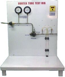
Vortex Tube Test Rig
The Vortex Tube Test Rig is one of the non- conventional methods of cooling which has no moving parts. It requires only source of compressed air. Through this tube, when air is admitted at high pressure, from one end, hot sir is discharged and from the other end, cold air comes out. The test rig is designed such that all the performance can be evaluated. CUSTOMER SCOPE Electrical power point 230 volts, 50 HZ, 1 ph, with 16 amps MCB. Clear space of 3 m x 2 m. Compressed air supply at 5 bar & 50 CFM LIST OF EXPERIMENTS • To understand the principle of working Vortex Tube. • To evaluate Adiabatic Efficiency of the system. • To evaluate C.O.P. of the system. • To find out Refrigeration Effect per kg of air supplied.
...more
VIBRATION MEASUREMENT & CALIBRATION SET UP
MECHANICAL SET UP SPECIFICATIONS: 1. With 0.5 HP PMDC Motor & Dimmer Speed Control. 2. Square Pipe Structure. 3. Two Fixed Stroke / Amplitude working: 10 mm and 20 mm max. 4. 30 X 30 x 0.8 cm Vibrating Platform.(Max. Test Load 5 Kgf) 5. Vibration Frequency from 1 to 15 Hz. 6. Powder Coated Finish. 7. Quantity: 1 Nos. ACCELEROMETER SPECIFICATIONS: 1. Display: Digital - 16 x 2 Alphanumeric LCD. 2. Range: a. For g : 10g. b. For f : 15 Hz. c. Displacement: 10 mm Or 20 mm - fixed. 3. Least Count: a. For g : 0.01g. b. For f : 1 Hz. c. Displacement : 1 mm. 4. Sensor: • Proximity Sensor Style Pickup: 1 no • LMPT style pick up – 1 no • Supply: 230V A. C. Single Phase – 50 Hz – Stabilized. 5. Enclosure: Powder Coated. 6. Quantity: 1 Nos.
...more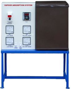
Vapour Absorption Test Rig
“Vapour Absorption Refrigerator” earlier known as “Electrolux” refrigerator is a self contained refrigerator working on absorption technology. In the absence of a compressor or pump, the circulation takes place by density difference. The system is pre-charged with three fluids namely water, ammonia and hydrogen. Hydrogen is used as an “inert gas” and does not undergo any phase change and heat transfer processes. Its purpose is to keep the pressure of the system constant. It uses an electrically operated generator, where, the ammonia vapours dissolved in water are separated and pure ammonia vapours enter the condenser. In the condenser, the high pressure vapours reject its latent heat to the surroundings and get liquefied. The liquid ammonia expands through expansion device where its pressure and temperature is reduced and cold low pressure vapour enters the evaporator where it absorbs heat from the space to be cooled and then vaporized ammonia absorbs in water. This strong solution then enters the generator and the cycle repeats. PRINCIPLE OF OPERATION Electrolux principle works on 3-fluid system. There is solution circulation pump. Total pressure is the same throughout the system. The third fluid remains mainly in the evaporator thus reducing partial pressure of refrigerant to enable it to evaporate at low pressure and hence low temperature. The schematic diagram of the Electrolux refrigerator working on NH3-H2O system with H2 as the third fluid is shown in figure. Liquid NH3 evaporates in the evaporator in the pressure of H2.Hydrogen is chosen as it is non –corrosive and insoluble in water. A thermosyphon bubble pump is used to lift the weak aqua from the generator to the separator. The discharge tube from the evaporator the generator is extended down below the liquid level in the generator. The bubbles rise and carry slugs of weak NH3-H2O solution into the separator. Two U-bends are provided as vapour- locks to prevent H2 from getting into the high side or solution circuit. Partial pressure of H2 provides the pressure difference of NH3 between the condenser and evaporator. Accordingly, we have: In condenser pure NH3 vapour pressure = Total pressure In evaporator NH3 vapour pressure = Total pressure - partial pressure H2 For example, consider the condenser temperature at 50 0C, and evaporator temperature as -15 0C. The corresponding vapour pressures of NH3 are: Condenser, Pk = 20.33bar; Evaporator outlet, Po2 = 2.6bar
...more
Universal Vibration Apparatus
This apparatus enables a comprehensive arrangement of vibration experiments to be conducted on a single Sturdy M. S. channel (100 mm x 50 mm) basic frame. The experiments are specially designed for quick and easy assembly on the frame. Many components are common to several experiments. AND THE WHOLE FRAME IS POWDER COATED. RANGE OF EXPERIMENTS PENDULUM EXPERIMENTS For pendulum experiments a sub-frame is attached to the upper beam of the frame. This pendulum supported frame is provided with hardened V guide for supporting the compound pendulum. It also carries two small chucks for gripping the wires for the bi-filer suspension and simple pendulum. Following experiments can be conducted. Expt. No. 1-Simple Pendulum To verify the relation T= 2 II S L/g & to plot the graph T2 V/s L Expt. No. 2-Compound Pendulum To verify the relation T= 2 II S k + (OG)/g(OG) To determine the radius of gyration & equivalent length of compound Pendulum. Expt. No. 3-Bi-filer suspension- (Tensional Oscillations) To determine the radius of gyration of body about the centre of gravity by using relation. T= 2 K/aSL/ g LONGITUDINAL VIBRATIONS • Expt. No. 4-Spring Mass System To verify the relation T= 2II SW/ Km .g and plot the graph T2 Vs W. • Expt. No. 5 -Equivalent Spring Mass System Study of undammed natural vibrations of beam pivoted at one end supported by tension spring at the other end. • Expt. No.6-Equivalent Spring Mass System Study of undammed natural vibrations of beam pivoted at one end supported by tension spring at the other end, plot the of graph amplitude Vs frequency. TORSIONAL VIBRATIONS • Expt. No. 7-Single Rotor To verify the relation T= 2II S I / Kt And to study the relationship between the periodic time & shaft length. • xpt. No. 8-Two Rotors To verify the relation T= 2II SIA + IB/Kt (IA+IB) And plot a graph of F Vs 1/ I 1 • Expt. No. 9-Single Rotor with Viscous Damping To find out the damping coefficient ‘Ct’ for various depth of damping drum (immersed in liquid) & to plot a graph of damping torque Vs depth of damping drum. • Expt. No. 10 To find out the natural frequency of beam with & without load & to verify the Dunkerley’s Rule. • Expt. No. 11 To study the forced vibrations for various amount of damping & to plot a graph of amplitude Vs frequency. ACCESSORIES • Exciter unit with fractional H. P. Electric Motor. • Ordinary strip chart recorder for recording vibrations. • Damper with arrangement for changing damping. SERVICE REQUIRED • Single Phase 15amp electrical Connection • Floor space area of about 2 m x 2 m
...more
Universal Governor Apparatus
The ‘J P T I’ unit consists of a main spindle driven by variable speed motor. Spindle can be fitted with four different governor assemblies. A scale with pointer is provided. We can calculate each characteristics of each governor at different speed and compare the performance. SPECIFICATION • Drive unit - D.C. motor 0 - 1500 R.P. M. • Watt, porter, Hartnell and Proell Governor. RANGE OF EXPERIMENTS • Watt, porter, Hartnell and Proell Governor. Determination of characteristics and comparison with theoretically predicate controlling force curves. Porter and Proell Governors:- • The effect of varying the mass of the centre sleeve. Proell Governors:- • The effects of varying the rotating mass. Hartnell Governor:- • The effects of varying the following parameter. Initial spring compression. SERVICE REQUIRED • Single Phase 15amp Electrical Connection. Suitable bench area for mounting the instruments.
...more
Two Stage Air Compressor Test Rig
The 'J.P.T.I' unit consist of one experimental type two stage reciprocating air compressor air cooled inter cooler ,suitable for a pressure of 12 kg/cm2 & having a displacement of 0.168 m3/min. driven by squirrel cage induction motor of 2 H.P. Energy meter & stop watch to determine the input to the motor. The above motor suited for 400/440 V. 3 ph. 50 cycles A. C. supply. The motor is provided with switch & starter. RANGE OF EXPERIMENT:- To conduct a performance test on the two stage reciprocating air compressor and to determine the volumetric efficiency and isothermal efficiencies at various delivery pressures. SPECIFICATION:- • Compressor: Two stage with intercooler. • Diameter of LP Cylinder: 55mm • Diameter of HP cylinder: 50 mm • Stroke Length: 65mm • Compressor Speed: 720 rpm • 2HP A/C Motor • Air intake Measurement: M/S Tank with Orifice-meter and Manometer • Bourdon Tube Pressure gauges to measure the pressures. • Three Phase energy meter. • Multi-channel temperature Indicator to measure various Temperatures. • Pressure relief valves. SERVICE REQUIRED:- • Suitable floor space to mount apparatus. • 32 amps Three Phase Electrical Connection.
...more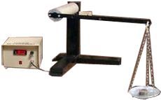
TORQUE MEASUREMENT MODULE
Measurement of Torque is a very essential phenomenon, because by nature itself Torque is a very difficult parameter to understand. Also Torque is a very important parameter from Design Engineers point of view. Because it is the key parameter for Hp & other related calculations for Motor or Gear Boxes etc. Here main aim is to demonstrate & explain about what Torque is & then how to measure it. SPECIFICATIONS 1. Torque Lever • Length: - 0.5 Meter • Material: - Mild Steel 2. Digital Indicator: - • Least Count: - 0.1 Kg-M • Digit: - 3 ½ 3. Weights: - Max 2 kg in steps of 100 gm
...more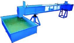
Tilting Flume
The 'J. P. T. I.' Tilting flume consists of a channel of size as in specifications. At the inlet a flow steadying section is provided so that there will be fewer disturbances at the test section. The gates provided at the upstream & downstream of the test section help to regulate the depth of flow. Depth measurements can be achieved with the help of a hook or point gauge mounted on a trolley which gives longitudinal and transverse movement. The slope of the bed can be adjusted to give positive or negative slopes. RANGE OF EXPERIMENT:- • Study of open channel flow with slope • Study of specific energy curve • Study of hydraulic jump • Study of Nappe profiles over a sharp crested weir • Calibration of sharp crested, Broad crested and ogee weir • Calibration of a Venturiflume • Study of flow under the sluice gate SPECIFICATION:- • A hydraulic flume of c/s 200x300 mm & 6000 mm length with transparent window on either sides of 1800 mm length. • Sliding gates one at upstream and other at the downstream side. • Screw jack for change of the slope of the flume. • A Sump tank of sufficient capacity. • Supply tank with waves damping arrangement. • A 3 H.P. centrifugal monoblock pump. • An Orifice meter with manometer to measure the discharge. Inlet/throat dimensions: 50/25 mm respectively. • Trolley with point gauge for level measurement. • Models supplied: • Sharp crested weir (crest length 200 mm) • Broad crested weir • Ogee weir or spillway. • Venturi flume SERVICE REQUIRED:- • Suitable Water supply. • Suitable floor space to mount apparatus. • 15 amps Single Phase Electrical Connection.
...more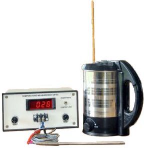
Thermocouple Calibration Test Rig
Here simple demonstration setup is provided to experiment with characteristics of Thermocouple. Here using this setup one can calibrate different types of thermocouples. SPECIFICATIONS 1. Water Bath with heating arrangement. 2. Thermocouple with necessary signal conditioning circuit. 3. Thermometer. 4. Measurement of oC and Mili Volt on Digital Display 5. Digital Indicator: - • Least Count: - 1 deg • Digit: - 3 1/2 6. Powder coated enclosure.
...more
THERMAL CONDUCTIVITY OF METAL BAR APPARATUS
The ‘J. P. T. I.’ unit consists of a copper bar, which is heated at one end, a Cold water jacket is provided at other end. The test section of bar is properly insulated and along the length of bar, thermocouples are attached. Heat conducted through the section of bar is measured by thermocouples and also heat dissipated in water measured by thermocouples. A panel comprising of controls and measurements is provided, which provides easy operation and study mounting of unit. SPECIFICATIONS:- • Material of metal bar - Copper • Length of the metal bar (Total) - 510 mm • Diameter of metal bar - 25.4 mm • Test length of bar - 292.5 mm • No. of thermocouples mounted on the bar - 6 • No. of thermocouples in the insulation shell - 2 • Heater - Band type • Cooling jacket diameter - 75 mm • No. of thermocouples - 10 • Position 1 to 6 - on the bar • Position 7 & 8 - in the shell. • Position 9 & 10 - cooling water in & out • Dimmerstat - 1000 watt • Voltmeter - 0 - 300 volt • Ammeter - 0 - 5 amp • Temperature Indicator - 0 – 3000 C SERVICE REQUIRED:- • Bench area to mount equipment • 15amps Single Phase, AC electric supply with earthing connection. • Continuous Water supply at constant head.
...more
Thermal Conductivity Of Insulating Powder
The ‘J.P.T.I.’ unit consists of two thin wall concentric copper spheres. The inner sphere houses the heating coil. Heating coil is made up of nichrome wire wound on mica sheet. The insulating powder packed between two shells. Power supply to the heater is given through a dimmerstat & is measured by voltmeter & an ammeter. Temperature can be measured with the help of thermocouples. Four thermocouple are embedded on inner sphere and six thermocouples are embedded on outer sphere. The entire ten temperature indicator, these reading enable of insulating powder. SPECIFICATION:- • Radius of the inner copper sphere - ri - 50mm • Radius of the outer copper sphere - ro - 100 mm • Voltmeter - 0 - 300 V • Ammeter - 0 - 5 A • Dimmerstat - 1000 watt • Heater - Mica Type. • Temperature indicator - 0 - 300 0C • Thermocouple - No. 1 to 4 on inner sphere to measure Ti • Thermocouple - No. 5 to 10 on outer sphere to measure T0 • Insulating powder Asbestos magnesia commercially available powder and • Packed between the two spheres. FEATURES:- • Thermal conductivity of insulating powder can be calculated. • Wide range of experiments can be performed to find value over a range of temperatures. • Ideal for group studies & demonstration. • Panelised instruments mounted on a control panel. • Easy to operate. • Useful for institutions, research laboratories & insulating powder manufactures EXPERIMENTS:- • To find out the thermal conductivity of the Insulating powder packed between the two spheres. SERVICE REQUIRED:- • 15 amps, Single Phase A. C. supply with earthing connection. • Suitable bench area to mount the instrument.
...more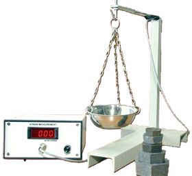
STRAIN MEASUREMENT
Basic cantilever beam is the best example so as to demonstrate effect of load so as to generate the strain. Here the fact is very well known that generated strain is directly proportional to load. The setup is provided with loading arrangement for cantilever beam with strain gauges and necessary signal conditioning circuit. SPECIFICATIONS 1. Cantilever beam • Capacity: - 2 kg • Material: - Mild Steel 2. Indicator: - • Least Count: -1 Micro Strain • Digit: - 3 1/2 3. Weights: - Max 2 kg in steps of 100 gm
...more
Stefan Boltzmann Apparatus
The ‘J. P. T. I.’ unit consists of a hemisphere surrounded by hot water. The instrument determines Stefan Boltzmann constant. Water heating tank is provided to supply hot water. Stefan Boltzmann constant is determined from the temperature raise rate when blacked disc is inserted at the centre of disc from hemisphere by radiation & its temperature begins to rise. SPECIFICATION:- • Hemisphere dia. - 0.205 m. • Base Bakelite plate - 0.05 m. • Test disc dia. - 0.0195 m. • Thickness of test disc - 0.003 m. • Thermocouples on hemisphere - 4 Nos. • Water tank of capacity with immersion heater. - 8 litre • Thermocouple on test disc - 1 No. • Temperature indicator. - 0-300 oC FEATURES:- • The phenomenon of heat transfer by radiation can be understood well. • Stefan Boltzmann constant can be calculated. • Easy to operate. • Ideal for group studies and demonstration. SERVICE REQUIRED:- • Suitable bench area to mount the instrument. • 15 amps, Single phase A. C. supply with earthing connection.
...more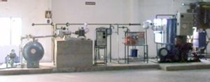
Steam Power Plant Lab
‘JPTI’ STEAM LAB (mini power plant) is rugged in construction. It employs all industrial components. But for the size it is a power plant. It is NON IBR Type boiler with single stage steam turbine. The plant is complete with condenser all measurement system, safety device, pipings, control systems etc. EXPERIMENTAL CAPABILITIES 1. Efficiency of Boiler 2. Heat Balance of Boiler 3. Various Efficiencies of Turbine 4. Heat Balance of Turbine 5. To plot curves of Pressure Vs Load 6. To plot curves of Steam flow rate Vs Load 7. To determine dryness fraction of Steam
...more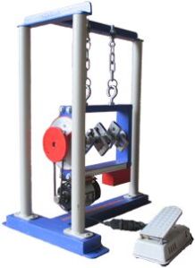
Static and Dynamic Balancing Apparatus
The ‘J P T I’ unit consists of a precision ground shaft rotating freely in ball bearing. For static balancing demonstration, an eccentric weight creates unbalance and value of relative weight require to balance the eccentric weight statically is determined. For dynamic balancing apparatus four weight assembly mounted on shaft is provided. Longitudinal and Angular position of weights are calculated from respective relative weight and the weight are mounted at the position. The rotation is vibration free when rotated by small motor. SPECIFICATION • Drive motor - Frictional horse power. • Four balances weight each containing a different sized “Eccentric” for varying the unbalance. • Additionally the containers, quality of precision made steel loading balls are supplied. FEATURES • Independent analysis of static and dynamic balancing. • Adjustable balance weights with variable moments. • Balance weight position accurately measured both radially and longitudinally. • Machine can be suspended on chains for dynamic balancing. • Completely portable and suitable for classroom demonstrations. RANGE OF EXPERIMENTS • Using the four weights provided Static balancing of the system using a moment polygon construction. • Dynamic balancing of the above system by calculating the position of the weights along the shafts, by resolving and taking moments about one end of the shaft. SERVICE REQUIRED • Single Phase 15amp electrical Connection. • Suitable floor space for instrument.
...more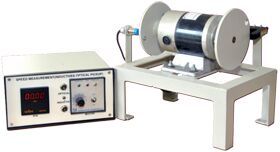
SPEED MEASUREMENT BY OPTICAL PICKUP
Here a simple setup is provided using which one can experiment with speed measurement characteristics of inductive type proximity switch. Here setup is supplied with PMDC motor & Speed controller unit. SPECIFICATIONS 1. Motor: - • Type: - variable speed • Speed: - 1000 rpm 2. Sensor: - • Type: - Optical 3. Speed Indicator • Range: - 30 to 9999 rpm 4. Speed Controller • Type: - Solid State
...more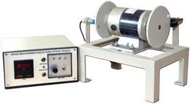
SPEED MEASUREMENT BY INDUCTIVE PICKUP
Here a simple setup is provided using which one can experiment with speed measurement characteristics of inductive type proximity switch. Here setup is supplied with PMDC motor & Speed controller unit. SPECIFICATIONS 1. Motor: - • Type: - variable speed • Speed: - 1000 rpm 2. Sensor: - • Type: - Inductive • Size: - M18 3. Speed Indicator • Range: - 30 to 9999 rpm 4. Speed Controller • Type: - Solid State
...more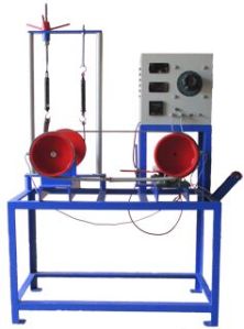
SLIP AND CREEP MEASUREMENT APPARATUS IN BELT DRIVE
The apparatus consists of a variable speed D.C. Motor. Driving Pulley and Driven Pulley of equal diameters. The pulleys are mounted on input shaft (motor shaft) and output shaft. The Driven pulley can slide on the base only with bearing block to change the initial tension in belt. Brake Drum is mounted on the output shaft, which helps to measure power output. The motor speed is varied by Dimmerstat. Driving and Driven pulley speeds are indicated by a two channel digital Speed Indicator. With the help of Stroboscope it is possible to demonstrate the slip of belt on Driving and Driven Pulley. SPECIFICATIONS • D.C. Motor- 1 HP, 1500 RPM, 230V variable Speed • Driving and Driven Pulleys of equal diameters (flat pulleys) • Brake Drum along with spring balance and rope arrangement is provided to load the system. • Flat belts of fixed length of following belt material. • Fabric Belt • Canvas Belt • Rubber Belt • Belt tightening arrangement - Bearing block is sliding and dead weight can be applied to set the initial tension in belt. • Speed Indicator: Two channel digital speed indicator with switch to change the channel. EXPERIMENTATIONS • To measure co-efficient of friction between pulley material and different belt materials • To measure power transmitted with varied belt tension and plotting a graph of (T1-T2) V/S (T1+T2) i.e. "Tension Characteristics". • To measure percentage slip at fixed belt tension by varying load on the Brake Drum and plot the graph of (T1-T2) V/s percentage slip i.e. ‘Slip Characteristics’. Finding a Creep Zone from graph. • To measure belt slip speed and observe the limiting value of load at constant speed when the slip just starts. SERVICE REQUIRED- • Single Phase 15amp Electrical Connection.
...more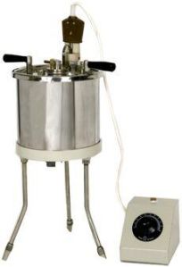
Saybolt Viscometer Apparatus
Used for determining the Viscosity of fuel oil and lubricating oil both thin & thick. The apparatus consists of Stainless Steel bath with oil cup which is centrally placed in a water bath. The bath has a lid which contains a water cooling tube, two handle with two stirrer blades, thermometer socket and a straight heater, stirring is done by turntable arrangement. A thermometer can also be inserted into the cup cover. The jets one universal and one Furol can be screwed to the cup by a handle (without strainer, withdrawal tube and glassware) can operate on 220 Volts AC mains. SERVICE REQUIRED:- • Fuel Oil OR Lubricating Oil sample. • Suitable Water. • Suitable Table space to mount apparatus. • 15 Amps. Single Phase Electrical Connection
...more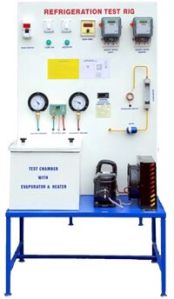
Refrigeration Test Rig
The Refrigeration Test Rig works on vapor compression cycle. The refrigeration (i.e. process of maintaining a closed space temperature below ambient temperature) is accomplished by continuously circulating, evaporating and condensing a fixed supply of refrigerant in a closed system. Evaporation occurs at a low temperature and low pressure while condensation occurs at a high temperature and pressure. Thus it is possible to transfer heat from an area of low temperature (in this case calorimeter) to an area of high temperature (the surroundings). The required instrumentation is provided to measure the various parameters at different points. This includes pressure gauges, temperature indicators and controller, energy-meters, heater for applying load and flow meter to measure the refrigerant flow . LIST OF EXPERIEMNTS: • To evaluate the cooling capacity in Watts & in Tons of the system. • To evaluate actual and theoretical C.O.P. of Vapor Compression Cycle. • To plot the actual Refrigeration Cycle on P-H chart. • To study various components and controls used in Vapor Compression Cycle.
...moreBe first to Rate
Rate ThisOpening Hours