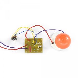
Light Dimmer DIY Kits
Get Price Quote
Light Dimmer DIY Kits (Not Soldered) A light dimmer works by essentially chopping parts out of the AC voltage. As the AC supply voltage increases at the beginning of the cycle, capacitor, C is charged through the series combination of the fixed resistor, R1 and the potentiometer, VR1 and the voltage across its plates increases. Once the triac has been fired into conduction, it is maintained in its “ON” state by the load current flowing through it, while the voltage across the resistor–capacitor combination is limited by the “ON” voltage of the triac and is maintained until the end of the present half-cycle of the AC supply. At the end of the half cycle the supply voltage falls to zero, reducing the current through the triac below its holding current, IH turning it “OFF” and the diac stops conduction. The supply voltage then enters its next half-cycle, the capacitor voltage again begins to rise (this time in the opposite direction) and the cycle of firing the triac repeats over again.

Camera Printed Circuit Board
Get Price Quote
Camera Printed Circuit Board
Best Deals from Circuit Boards

Printed Circuit Boards
Get Price Quote
Printed Circuit Boards